


Parallel Compressor Systems Installation & Operations Manual, October 2004 17
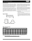
Parallel Compressor Systems
Warning: It is illegal to knowingly vent or discharge
any CFC’s and HCFC’s to the atmosphere.
ALL CFC’s and HCFC’s must be reclaimed
or recycled.
Leak Check
1. To check the systems for leaks, leave all valves closed on
suction, liquid and hot gas manifolds. The unit is shipped
with a holding charge of dry nitrogen and should be leak
free. Build up the pressure in each circuit to a maximum of
150 psig dry nitrogen and check each individual circuit.
2. After each circuit has been checked, open all valves
to allow the pressure into the unit assembly. Check to
be sure pressure is throughout the assembly. Check all
connections and accessories for leaks.
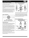
Evacuation
1. After the system is leak checked, connect a good high
vacuum pump with fresh oil to both the low and high
side evacuation valves. Connections between the pump
and evacuation valves should be made with copper
tubing or high vacuum hose having a diameter of at least
3/8”. Evacuate the system to 1500 microns for the rst
evacuation.
2. After each evacuation, the vacuum should be broken by the
introduction of refrigerant into the system. The refrigerant
should be passed through a drier when breaking the
vacuum until the pressure is brought up to 0 psig.
3. Between the first and second evacuation, the liquid
lter driers and suction lters should be installed in each
replaceable core shell.
4. A triple evacuation is recommended. The third and nal
evacuation should achieve a value of 500 microns or less.
After this vacuum is reached, add as much refrigerant as
possible into the receiver. Now the system is ready to be
started.
Start-up
1. Set all pressure controls as recommended elsewhere in this
manual. Recheck all service valves and shut-o valves to
be sure they are open.
2. Check and be sure the condenser fan motors are running
in the correct rotation.
3. All evaporator fan motors should be checked for proper
rotation. The fans in low temperature boxes generally have
a fan delay for defrost purposes that keep the fans from
operating until the evaporator coil has reached a certain
temperature. It will be necessary to jump-out the fan
controls on freezer units to make them run through nal
charging and room temperature pull-down. The wiring
diagram for the unit will have to be consulted to determine
how to best force the fans to operate for this step.
4. With all compressor and control breakers and toggle
switches turned o, apply power to the unit. If the unit is
using a phase monitor, the green light must come on before
going any further. (See instructions for phase protector
elsewhere in this manual.) A red light indicates incorrect
phasing or voltage. Check with a volt meter to see if correct
voltage is connected to the unit. Correct the Power Supply
before proceeding.
5. Turn on the circuit breaker for the control power. If an
electronic control system is installed on the unit, it will
initiate at this time. The Heatcraft preferred controller is
manufactured by Computer Process Control (CPC). Review
the manual for the controller supplied with the system.
6. Turn on circuit breakers to all compressors. The compressors
can be started by turning on the compressor toggle
switches. Likewise, each circuit control can be started by
turning on the circuit toggle switch. It is recommended that
one compressor at a time be started and checked before
allowing them all to operate. It is also advisable to check
one circuit at a time to be certain all components work
when called upon and that the circuit wiring is correct.
7. When each circuit and compressor has been tested and
the appropriate amount of refrigerant has been added for
proper operation, allow the system to operate and pull-
down the room/xture temperatures.
8. Once the system is operating, set all regulating valves.
9. When the room and/or the fixture temperatures are
at design, the expansion valves should be set. (See
instructions elsewhere in this manual.)
10. Adjust the electronic or manual pressure controls
as necessary to maintain proper pressures and
temperatures.
11. Check the refrigerant level in the receiver. The minimum
level that should be maintained is 20%.
12. All circuit defrost controls must be set and checked. Again,
one circuit at a time should be tested.
13. Set condenser fan controls to maintain the proper discharge
pressure.
14. All safety controls should be checked and veried. Check
that the alarm circuitry is operating at this time.
15. Check the oil reservoir during the start-up and add oil as
necessary. The oil level should be between the upper and
lower reservoir sight glass. Do not add more than two
gallons of oil to a system. If more oil is needed, recheck the
piping as oil is not returning to the unit properly.
Leak Checking, Evacuation and Start-up