


24 Part # 25000102
Installation and Operations Manual
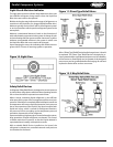
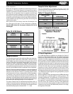
For Relief Devices set at 400 psig
• Obtain the capacity at 400 psig setting
• Locate this capacity or the nearest larger capacity in the left-hand column of the discharge piping table above and read across to obtain the maximum lengths
for each tube and pipe size
For relief devices set at 350 psig, use the above table and multiply by .75 to determine maximum lengths
For relief devices set at 425 psig, use the above table and multiply by 1.15 to determine maximum lengths
For relief devices set at 450 psig, use the above table and multiply by 1.25 to determine maximum lengths
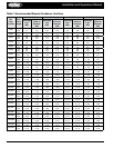
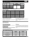
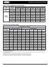
Table 17. Henry Relief Valve Capacity Rating
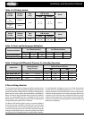
Table 18. Discharge Piping Table
Type
Catalog
Number
Size Connection Standard Pressure Settings PSIG
Inlet Outlet 350 400 425 450
Angle
526E 3/8 MPT 3/8 FLARE 10.2 11.6 12.3 13.0
527E 1/2 MPT 5/8 FLARE 28.5 32.4 34.4 36.3
Straight
Through
5231 3/8 MPT 3/8 FLARE 11.2 12.7 13.5 14.3
5231-A 3/8 MPT 1/2 FLARE 18.6 21.1 22.4 23.7
5231 1/2 MPT 5/8 FLARE 18.6 21.1 22.4 23.7
5232 1/2 MPT 5/8 FLARE 28.1 32.0 33.9 35.8
5240-1/2 1/2 MPT 3/4 FPT 41.2 46.8 49.1 52.5
5242-3/4 3/4 MPT 3/4 FPT 41.2 46.8 49.1 52.5
5244-1 1 MPT 1 FPT 74.0 84.2 89.3 94.4
5246-1-1/4 1-1/4 MPT 1-1/4 FPT 129.7 147.5 156.4 165.4
Maximum Length of Discharge Pipe in Feet
* For 400 PSIG Pressure Setting
Relief Device
Capacity
Lbs. Air/Min.
Soft Copper Tube (OD) Schedule 40 Pipe
3/8” 1/2” 5/8” 1/2” 3/4” 1” 1-1/4” 1-1/2” 2”
10 3-1/2 19-1/4 61 108 445
12 2-1/2 12-1/4 44 75 308
14 2 9-1/2 32 56 228
18 5-1/4 19-1/4 33 137
20 4-1/4 16 28 110 371
25 2-1/2 9-1/2 18 72 238
30 2 7 12 49 165
35 2 5-1/4 9 37 121
40 3-1/2 7 28 93 366
50 2-1/2 4 18 60 233
70 3 9 30 119 257
80 2 7 23 91 198
90 2 5 18 72 156
125 3 10 37 81 282
150 2 7 26 56 196