


Parallel Compressor Systems Installation & Operations Manual, October 2004 19
Parallel Compressor Systems
Electronic Control System
The electronic controller has become the standard on
parallel compressor systems. The increased capabilities of the
controllers magnify the eciency of the parallel compressor
system making it a very attractive accessory item.
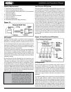
The electronic control system preferred by Heatcraft is the
Computer Process Control (RMCC) controller. The RMCC oers
a complete control and monitoring package through one or
more input boards (16AI). The controller continuously monitors
the parameters for refrigerant pressures, defrost operation,
temperature control, and system alarms.
As the RMCC monitors the system in operation, it compares the
reported values against programmed set points it is to maintain,
thus cycling compressors, unloaders, condenser fans, defrost
periods and sounding alarms as required.
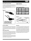
Interface with the actual devices being controlled is through
one or more pressure transducers, watt transducer, temperature
sensors, refrigerant sensors, humidity sensors, refrigerant level
sensor, phase loss and output boards (8R0). The 8RO boards
can be mounted remotely for lower installation cost, when
controlling devices such as air cooled condensers. These
boards are connected to the RMCC via a three wire network
and are purchased as needed for the application. Remote
communications capabilities is standard with the RMCC through
a modem that is supplied.
System Balancing
Important: In order to obtain the maximum capacity
from a system, and to ensure trouble-free
operation, it is necessary to balance each
and every system.
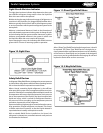
System Superheat
This is extremely important with any refrigeration system. The
critical value that must be checked is suction superheat
Superheat is not preset at the factory.
Suction superheat should be checked at the compressor as
follows:
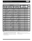
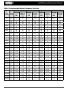
1. Measure the suction pressure at the suction service valve of
the compressor and determine the saturation temperature
corresponding to this pressure from a “Temperature-
Pressure” chart.
2. Measure the suction temperature of the suction line about
one foot back from the compressor using an accurate
thermometer.
3. Subtract the Saturated temperature from the actual suction
line temperature. The dierence is Superheat.
If suction superheat is too low, it can result in liquid refrigerant
being returned to the compressor. This will cause dilution of
the oil and eventual failure of the bearings and piston rings.
In extreme cases, the compressor will fail as a result of the
diluted oil.
High suction superheat will result in excessive discharge
temperatures that can cause a breakdown of the oil. This action
results in piston ring wear, piston and cylinder wall damage.
Also, as the superheat increases, the suction pressure decreases
resulting in reduced capacity. For maximum system capacity,
suction superheat should be kept as low as is practical. Heatcraft
recommends that the superheat at the compressor be no lower
than 20°F.
If adjustments to the suction superheat need to be made, the
expansion valve at the evaporator should be adjusted. See
instructions in next section.
Evaporator Superheat
Check Your Superheat after the box temperature has reached
or is close to reaching the desired temperature, the evaporator
superheat should be checked and adjustments made if
necessary. Generally, systems with a design TD of 10°F should
have a superheat value of 6° to 10° F for maximum eciency.
To properly determine the superheat of the evaporator, the
following procedure is the method Heatcraft recommends.
1. Measure the temperature of the suction line at the point the
bulb is clamped.
2. Obtain the suction pressure that exists in the suction line at
the bulb location by either of the following methods:
a) A gauge in the external equalized line will indicate the
pressure directly and accurately
b) A gauge directly in the suction line near the evaporator
or directly in the suction header of the evaporator will
yield the same reading as above
3. Convert the pressure obtained in 2a or 2b above to saturated
evaporator temperature by using a temperature-pressure
chart.
4. Subtract the Saturated temperature from the actual suction
line temperature. The dierence is Superheat.
Alternative Superheat Method
The most accurate method of measuring superheat is found
by following the previous procedure, Temperature/Pressure
method. However, that method may not always be practical.
An alternative method which will yield fairly accurate results is
the temperature/temperature method.
1. Measure the temperature of the suction line at the point the
bulb is clamped (outlet).
2. Measure the temperature of one of the distributor tubes
close to the evaporator coil (inlet).
3. Subtract the outlet temperature from the inlet temperature.
The dierence is approximate Superheat.
This method will yield fairly accurate results as long as the
pressure drop through the evaporator coil is low.