


22 Part # 25000102
Installation and Operations Manual
Carlyle
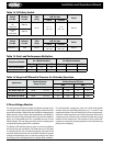
Part No.
Danfoss
Part No.
Time
Delay
Pressure
Di. Psi (bar)
Reset
Cut-In Cut-Out
634-2008
OR
P529-2130
60B2101
45 sec.
8 – 11
(.55 - .76)
4 - 8
(.28 - .55)
Manual
634-2050
OR
P529-2100
60B2151
Carlyle
Part No.
Johnson
Part No.
Time
Delay
Pressure
Di. Psi (bar)
Reset
Cut-In Cut-Out
O6DA660115 P345 45 sec.
8 – 11
(.55 - .76)
4 - 8
(.28 - .55)
Manual
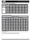
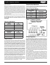
Compressor Model
Multiplication Factor
For 1 Bank Unloaded
Multiplication Factor
For 2 Bank Unloaded
Capacity Power EER Capacity Power EER
All 4 Cylinder Models .49 .57 .86 - - -
All 6 Cylinder Models .67 .73 .92 .32 .46 .70
Application
Suction Pressure
Range Psi (bar)
P Required-Discharge Minus
Suction Pressure Psi (bar)
O6D O6E
L.T. R-502, 404A, 507 10-25 (1.7-2.7) 30 (2.1) 30 (2.1)
M.T. R-502, 404A, 507 30-60 (3.1-5.2) 40 (2.8) 45 (3.1)
L.T. R-12, 134A 10-30 (1.7-3.1) 30 (2.1) 35 (2.4)
M.T. R-22 or H.T. R-22 30-90 (3.1-7.2) 50 (3.5) 55 (3.8)
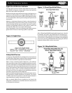
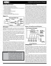
3-Phase Voltage Monitor
The microprocessor-based voltage and phase sensing circuit
constantly monitors the three phase voltages to detect harmful
power line conditions. When a harmful condition is detected, the
phase monitor output relay is deactivated after a specied trip
delay. The output relay reactivates after power line conditions
return to an acceptable level for a specied amount of time
(Restart Delay). The trip delay prevents nuisance tripping due
to rapidly uctuating power line conditions.
The Bicolor LED indicator light is green in normal conditions
and red during trip conditions. On initial start-up, if the light
is continuously red, the unit electrical phase may need to be
reversed. Each main power line should be checked for proper
voltage and imbalance prior to reversing a phase. Also check
the settings of the Voltage Monitor for proper eld condition.
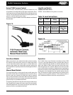
For semi-hermetic compressor units, two of the three power
monitor leads on the Voltage Monitor to L1, L2, and L3 may
need to be switched. For units with Scroll
®
or Screw compressors,
which are rotation sensitive, two of the main power lines to the
compressor unit will have to be switched to match the correct
rotation of the compressors. The rotation of Screw and Scroll
®
compressors has been properly phased in the manufacturing
plant prior to shipping.
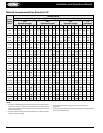
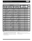
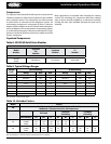
Table 14. Oil Safety Switch
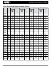
Table 15. Part Load Performance Multipliers
Multiply compressor rating data by above factors when used with blocked suction unloading
Table 16. Required Dierential Pressure for Unloader Operation