


Parallel Compressor Systems Installation & Operations Manual, October 2004 7
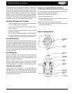
Ventilation Requirements
Indoor Units
If compressors or condensing units are located in a machine
room, adequate ventilation air must be provided to avoid
an excessive temperature rise in the room. To allow for peak
summer temperatures a 10°F temperature rise is recommended,
although a 15°F rise might be acceptable.
With compressors with remote condensers, approximately 10%
of the heat rejected is given o by the compressor casting and
the discharge tubing. The correct formula for calculating the
ventilation requirement of the Indoor Parallel unit is:
CFM = 10% of THR / hr
10° TD
The air intake should be positioned so that air passes over the
units. All State, Local, and National codes should be followed.
Electrical
To insure the proper operation of equipment and reduce the
possibility of interruption of refrigeration due to electrical
power failure, the following precautions must be observed:
• All electrical work must be done in accordance with the
National Electrical Code and existing local codes
• The power supply must be the same as specied on the unit
data plate
• An adequate power supply must be provided
• Voltage uctuations in excess of 10 percent must
be corrected
• Overload relays (Carrier compressors only) are selected
in accordance with specied limits as determined by the
motor-compressor manufacturer. They must not be changed
in size or shorted-out
• Control panels must be provided with a single phase, 60
Hertz supply. See the unit wiring diagram for the voltage
requirement
• Before starting up a parallel unit, insure that all fuses and
motor-protective devices are in place and that all wiring is
secure. A complete wiring diagram for troubleshooting the
unit will be found inside the control panel cover
Refrigerant Piping
The system as supplied by Heatcraft, was thoroughly cleaned
and dehydrated at the factory. Foreign matter may enter the
system by way of the eld piping required. Therefore, care must
be used during installation of the piping to prevent introduction
of foreign matter.
Install all refrigeration system components in accordance with
all applicable local and national codes and in conformance
with good practice required for the proper operation of the
system.
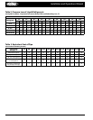
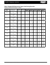
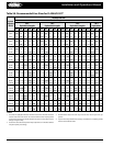
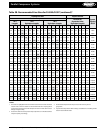
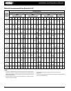
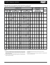
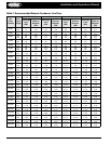
Proper size refrigeration lines are essential to good refrigeration
performance. Suction lines are more critical than liquid or
discharge lines. Oversized suction lines may prevent proper oil
return to the compressor. Undersized lines can rob refrigeration
capacity and increase operating cost. Consult the line sizing
charts in this manual for proper pipe sizes.
The following procedures should be followed:
1. Do not leave dehydrated compressors or lter-driers open
to the atmosphere
2. Use only refrigeration grade copper tubing, properly sealed
against contamination
3. Suction lines should slope 1/4” per 10 feet towards the
compressor
4. Discharge lines should slope 1/4” per 20 feet toward the
condenser
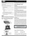
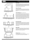
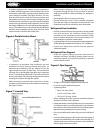
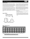
Suction P-Traps
• Provide P-Traps at the base of each suction riser of four (4)
feet or more to enhance oil return to the compressor. Use a
P-Trap for each 20 feet section of riser. See Figure 4 below:
*The P-Trap should be the same size as the horizontal line
See Figure 5 below
Parallel Compressor Systems
Figure 4. P-Trap Requirements
Figure 5. P-Trap Construction