


32 Part # 25000102
Installation and Operations Manual
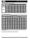
must be varied during the setting procedure and it is dicult
to determine exactly when the bypass valve opens unless a
pressure gauge can be located at the valve outlet.
Therefore, sucient load must be available in some form to
raise the suction pressure above the desired valve setting. Once
this is accomplished, the load can be slowly decreased until the
DBV opens (a hissing sound and/or an accompanying pressure
rise at the outlet connection will indicate that the bypass valve
has opened).
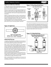
Alco Controls
Valve Setting and Adjustment
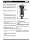
CPHE and DGRE regulators are commonly used to prevent the
suction pressure from falling below a predetermined set point.
Complete information about these valves can be found in ALCO
CONTROLS Catalog 24-D.
The rst step after installation is to determine the set point for
the minimum suction pressure allowable for the application.
The following procedure should be followed.
1. Start the system and determine if it is operating properly:
Install a gauge on the compressor suction line and measure
the suction pressure after the system has stabilized. To make
certain that hot gas is not being bypassed, listen to the main
regulator ow or feel the outlet piping. If the piping is warm,
this would indicate hot gas is owing.
2. Stop the flow of hot gas by de-energizing the hot gas
solenoid valve or by turning the power assembly adjusting
stem full CounteRCloCkwise.
3. Reduce the evaporator load until the suction pressure lowers
to the point at which bypass is desired.
4. If the hot gas solenoid was de-energized to stop hot gas
ow, make sure it is now energized.
5. Turn the power assembly adjusting stem in a CloCkwise
direction until bypass occurs and suction pressure does
not fall below the predetermined set point. A CloCkwise turn
of the adjusting stem will increase the pressure setting; a
CounteRCloCkwise turn will decrease it. Standard pressure pilot
is adjustable from 0 to 80 psig, with one complete turn equal
to approximately 4 psi change. Adjustments should be made
in small increments, allowing for the system to stabilize after
each turn.
6. Vary the evaporator load to test at various conditions that
the suction pressure does not fall below the predetermined
set point.
7. Replace the seal cap on the adjusting stem.
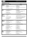
Control Settings
The following tables are for use when mechanical low pressure
switches are incorporated for rack pressure control. All control
settings are approximate and should be adjusted for actual
eld conditions and equipment. All settings are based on 10°F
TD evaporator.
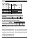
Low Pressure Switch Setting for RMCC
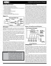
Some systems use a form of electronic control such as CPC’s
RMCC solid state controller for Rack operation. On these
systems, there is one mechanical low pressure control for each
suction group that may be on the rack. This control is for backup
emergency control in the event of a board or other electronic
component failure. This low pressure control must be set for the
minimum suction pressure that the rack would be expected to
operate at to keep from interfering with the RMCC control.
Example, for a low temperature suction group, this control
should be set for 0 - 2 psig cutout and approximately 10 psig
cutin. A medium temperature suction group can be set higher.
In the event that this control is needed to actually control the
compressors, set the cutin and cutout for the suction pressure
that you want the compressors to operate to maintain case or
box temperatures.
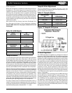
NOTE: This low pressure control will generally be
mounted on a compressor with the braided
stainless steel tubing connecting to the
appropriate suction group header.
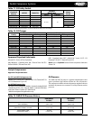
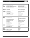
Table 30. Control Settings for R-404A/R-507
Air Temp
°F
EPR
psig
LP C/I
psig
LP C/O
psig
38-42 69 72 64
34-38 64 66 57
34-36 60 62 55
33-35 59 61 53
28-32 55 58 50
24-28 48 50 35
-10-/0 21 24 15
-10-/-5 20 22 14
-15-/-10 15 17 14
-20-/-15 12 15 8
Table 31. Control Settings for R-22
Air Temp
°F
EPR
psig
LP C/I
psig
LP C/O
psig
38-42 54 57 50
34-38 50 48 43
34-36 47 50 41
33-35 45 47 40
28-32 43 45 38
24-28 36 38 25
-10-/0 13 17 8
-10-/-5 11 14 7
-15-/-10 8 10 5
-20-/-15 5 8 2