


2 Part # 25000102
Table of Contents
Introduction ..............................................................................................................3
Inspection
Unit Designation
Model Denition
System Warranty .......................................................................................................4
Rigging
Location of Equipment - INDOOR
Clearances
Floor & Foundation Requirements
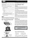
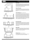
Vibration Mounts
Figure 1. Vibration Pad & Spring Isolator
Figure 2. Vibration Pad Locations
Location of Equipment - OUTDOOR ........................................................................5
Ground Mounting
Roof Mounting
Unit Vibration Isolation
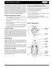
Compressor Spring Vibration Isolators
Figure 3. Spring Mount
Unit Access ................................................................................................................6
Vertical Clearance
Lateral Clearance
Decorative Fences
Units in Pits
Multiple Units
Ventilation Requirements ........................................................................................7
Electrical
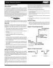
Refrigerant Piping
Suction P-Traps
Figure 4. P-Trap requirements
Figure 5. P-Trap construction
Figure 6. Double Suction Risers ...............................................................................8
Figure 7. Inverted Trap
Refrigerant Line Insulation
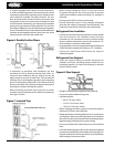
Refrigerant Line Support
Figure 8. Pipe Support
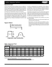
Expansion Loops .......................................................................................................9
Figure 9. Osets
Table 1. Expansion Chart
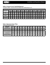
Table 2. Pressure Loss of Liquid Refrigerants .......................................................10
Table 3. Equivalent Feet of Pipe
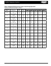
Table 4. Weight of Refrigerants in Copper Lines During Operation ...................11
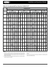
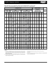
Table 5A. Recommended Line Sizes for R-404A and R-507 ................................12
Table 5B. Recommended Line Sizes for
R-404A and R-507 (continued) ..............................................................13
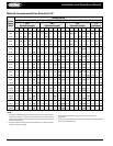
Table 6A. Recommended Line Sizes for R-22 ........................................................14
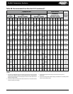
Table 6B. Recommended Line Sizes for R-22 (continued) ...................................15
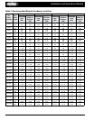
Table 7. Recommended Remote Condenser Line Sizes .......................................16
Leak Checking, Evacuation, and Start-up .............................................................17
Refrigerant Distribution ........................................................................................18
O-Cycle
Electric Defrost
Priority I Hot Gas Defrost
Head Pressure Control System
Electronic Control System ......................................................................................19
System Balancing
System Superheat (NOTE: Superheat is not preset at factory)
Evaporator Superheat
Alternative Superheat Method
Compressors ...........................................................................................................20
Copeland Compressors
Table 8. 3D/4D/6D Solid State Modules
Table 9. Typical Voltage Ranges
Table 10. Unloader Factors
Table 11. Oil Safety Switch .....................................................................................21
Table 12. Oil Charges
Approved Copeland Lubricants
Carlyle Compressors
Approved Carlyle Lubricants
Oil Pressure
Table 13. O6D/E Oil Pressure History
Table 14. Oil Safety Switch .....................................................................................22
Table 15. Part Load Performance Multipliers
Table 16. Required Dierential Pressure
Three-Phase Voltage Monitor
Sight Glass & Moisture Indicator ...........................................................................23
Figure 10. Sight Glass
Safety Relief Devices
Figure 11. Direct Type Relief Valves
Figure 12. 3-Way Relief Valve
Table 17. Henry Relief Valve Capacity Ratings .....................................................24
Table 18. Discharge Piping Table
Series P100 Pressure Control .................................................................................25
Figure 13. P100 Pressure Controls
Auto Reset Models
Manual Reset Models
Liquid Level Switch
S-9400 Level Switch Series
Table 19. Level Switch Table
Figure 14. S-9400
S-9400 Operation
Module Replacement .............................................................................................26
Figure 15. Module Replacement
Oil Control
Low Pressure Oil System
Figure 16. Low Pressure Oil System
Oil Separators
Table 20. AC&R Models...........................................................................................27
Temprite Models
Temprite Valve Adjustment
Table 21. Temprite Models
Figure 17. Temprite Oil System
Oil Level Regulators
Table 22. AC&R Model Regulators .........................................................................28
Troubleshooting Oil System
Liquid Filter-Driers & Suction Filters
Table 23. Sporlan Valve Company
Table 24. Alco Controls
Suction Filter ...........................................................................................................29
Compressor Motor Burnout Clean-up Procedure
Sporlan Valve Company
Superior Valve Company ........................................................................................30
Table 25. Type F Filter
Table 26. Type DF (for clean-up)
Alco Controls
Table 27. Type AF Filter
Table 28. Type AFD (for clean-up)
Head Pressure Control
Valve Functions
Liquid Drain Control Method .................................................................................31
Recommended Valve Settings
Table 29. Pressure Range, Set Point & Change per Turn
Field Adjustment
Hot Gas Bypass Regulator Adjustment
Sporlan Valve Company
Valve Setting and Adjustment
Alco Controls ...........................................................................................................32
Valve Setting and Adjustment
Control Settings
Table 30. Control settings for R-404A/R-507
Table 31. Control settings for R-22
Low Pressure Switch Setting for RMCC
General Maintenance Schedule.............................................................................33
SERVICE DIAGNOSIS CHART .............................................................................34-35
Service Record ........................................................................................................36
System Reference Data
© 2007 Heatcraft Refrigeration Products LLC
Installation and Operations Manual