


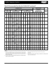
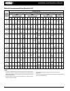
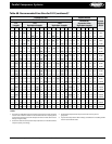
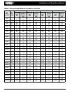

Parallel Compressor Systems Installation & Operations Manual, October 2004 3
Parallel Compressor Systems
Introduction
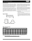
Parallel Compressor systems are central refrigeration units
employing 2 to 8 parallel piped compressors, a control panel,
and receiver mounted on one common base frame. The system
may be designed for either Indoor or Outdoor use. The Outdoor
design may include the condenser mounted and piped.
The selection and design of the system is based on the needs
of the individual customer. The most important point in
planning an installation of the Heatcraft parallel system is the
proper selection of the system components for the particular
application.
Component parts have been selected for their dependability
and availability to keep service problems to a minimum.
Simplicity of design has also made the Heatcraft parallel
system one of the easiest to service and install. The simplicity
and compactness of the Heatcraft design make the addition of
hot gas defrost and/or heat reclaim a simple and economical
feature.
In the following pages will be found explanations of system
components, wiring and piping diagrams, control settings, and
operational guides.
Inspection
Unit inspection should be assigned to a dependable individual.
Inspect the parallel system and any accessories shipped with
them for damages or shortages before and during unloading.
All items on bill of lading should be accounted for prior to
signing the shipping receipt. Note any shortages or damage on
carrier’s delivery receipt (Specify the extent and type of damage
found). Unit should be inspected carefully for concealed
damage. Notify the Heatcraft sales representative and the
carrier of the damage immediately. Request an immediate
joint inspection with the carrier (Do not repair the unit until
inspected by carrier’s representative). Care should be exercised
when uncrating units to prevent damage.
The system is shipped with a holding charge of dry nitrogen.
Check to see that pressure is still in the unit upon receipt.
Report lack of pressure immediately to the Heatcraft service
department.
NOTE: Accessory items such as drier cores,
mounting pads, modems, etc. may be
packaged in a separate carton. Be sure
that you receive all items.
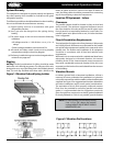
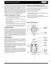
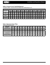
Unit Designation
Units are identied by letter, brand, compressor type, quantity
of compressors, horsepower, condenser type, control voltage,
defrost type, refrigerant/range, unit voltage and application.
Unless otherwise requested by the customer all refrigeration
circuits are numbered from one to the highest and from left to
right while facing the electrical panel.
Model Denition:
1st digit - Brand (B, C, H, or L)
2nd digit - Compressor Type
H - Hermetic
R - Reciprocating
S - Screw
O - Open
Z - Scroll
®
C - Compound
3rd digit - Unit Construction
R - Remote Condenser
U - Attached Condenser
H - Hybrid
M - Multi-compressor Platform
F - Frame Hybrid (Frame + Standard Unit)
4th digit - Compressor Quantity
2 - 2 Compressors
3 - 3 Compressors
4 - 4 Compressors
Etc.
5th, 6th, & 7th digit - Horsepower
030 - 30 HP
075 - 75 HP
100 - 100 HP
Etc.
8th digit - Condenser Type
A - Air
W - Water
E - Evaporative
9th digit - Control Voltage
A - 115/1/60
B - 208-230/1/60
C - 24/1/60
10th digit - Defrost Type
A - Air/O-Cycle
E - Electric
G - Hot Gas
M - Multiple
W - Water
11th digit - Temperature Range
L - Low
M - Medium
H - High
C - Combination
X - Ultra Low
12th digit - Refrigerant Type
2 - R-22
4 - R-134A
6 - R-404A, R-507
8 - Multiple
13th digit - Unit Voltage
C - 208-230/3/60
D - 460/3/60
E - 575/3/60
J - 208/3/60
K - 230/3/60
M - 380/3/60
14th digit - Application
1 - Indoor
2 - Outdoor