


Parallel Compressor Systems Installation & Operations Manual, October 2004 9
In order to compensate for the expansion of the tubing, it
is necessary to estimate the amount of expansion and then
provide osets or loops in the refrigerant piping. Normally the
area to be most concerned with is the straight line distance
from the xture to the parallel compressor unit.
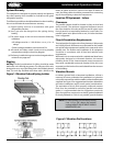
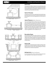
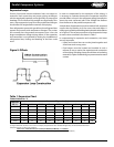
A simple form of expansion loop can be made of soft tempered
copper tube by bending it to the correct size and shape. A
neater type is made by assembling hard tube with solder elbows
as in Figure 9. The correct proportions of such expansion loops
to meet various conditions are shown in Table 1.
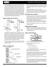
In compensating for expansion and contraction, two items
are very important:
Liquid and suction lines can not be joined together and
should not touch at any point
Pipe hangers must be located and installed in such a
manner as not to restrict the expansion and contraction
of the tubing. All tubing clamps should have an insulating
material (i.e. Hydra Sorb bushing) to prevent metal to metal
contact
•
•
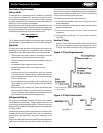
Expansion Loops
Suction, liquid and remote condenser lines are subject to
expansion and contraction and proper piping techniques
must be employed (especially on hot gas lines) to prevent line
breakage. This is critical on long straight runs of generally 70’ or
more where expansion loops must be provided and hangers
should allow for longitudinal movement of the piping.
On a refrigeration system with gas defrost, the refrigerant lines
expand and contract with temperature changes. The suction
line normally has the greatest movement since it has the
largest temperature change during defrost. If the expansion
and contraction is not planned for during the installation of
refrigeration lines, kinking and breaking of the lines could
occur.
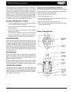
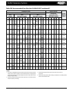
Parallel Compressor Systems
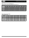
Ref. Line
OD (in.)
Amount of Expansion (in.)
1/2 1 1-1/2 2 2-1/2 3 4 5 6
7/8 10 15 19 22 25 27 30 34 38
1-1/8 11 16 20 24 27 29 33 38 42
1-3/8 11 17 21 26 29 32 36 42 47
1-5/8 12 18 23 28 31 35 39 46 51
2-1/8 14 20 25 31 34 38 44 51 57
2-5/8 16 22 27 32 37 42 47 56 62
Figure 9. Osets
Table 1. Expansion Chart
Table of Values for “L”
NOTES: Calculations for expansion and contraction should be based on the average coecient of expansion of copper which is .0000094
per degree Fahrenheit between 77°F and 212°F. Example, the expansion for each 100 feet of length of any size of tube heated from room
temperature of 70°F to 170°F, a rise of 100°F, is:
100°F (rise °F) X 100 (linear feet) X 12 (inches) X.0000094 (coecient) = 1.128 inches
(Reprinted from Copper & Brass Research Association)