


Parallel Compressor Systems Installation & Operations Manual, October 2004 27
Parallel Compressor Systems
to the compressor.
Before the oil separator is installed, an initial charge of oil must
be added to it. This initial charge of oil is the amount that is
needed to just oat the needle valve oat. This amount of oil
will stay in the oil separator when in operation and will seal
the needle and prevent damage to the oat mechanism. Oil
Precharge is very important. Failure to Precharge the separator
sump may result in damage to the oil return oat mechanism
by the turbulent hot gas bouncing the oat and causing the
needle valve to leak.
New systems from the factory have been Precharged. Use
the same type of oil that is in the compressor crankcase.
See the table below for the proper amount of oil to be
Precharged.
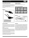
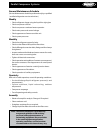
Temprite Models
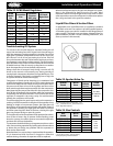
The Temprite brand used is the coalescent lter type separator.
Because this lter is ner than a lter/drier, it will pick up any
and all euent and dirt circulating in the system down to 0.3
microns. These lters should be changed after 24 to 48 hours
of initial run time. A second lter is supplied with the system
for this purpose. If the lter becomes dirty, it will not function
at its optimum performance level. In the event of a compressor
burnout, all the euent will be contained in the oil separator.
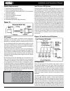
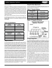
When the Temprite coalescent separator is used, the separate oil
reservoir is not required. The oil separator serves the additional
function as the reservoir. There is a constant pressure valve
used between the oil return outlet and the oil level regulators
to maintain a low pressure oil flow to the regulators. This
valve should be adjusted to maintain oil pressure to the level
regulators at 20 psig higher than the highest suction pressure
group. This valve can be adjusted by removing the external cap
and rotating the adjusting spring in or out as required.
The valve currently used is manufactured by Parker and is a
model A7 constant pressure expansion valve with a range of 0
to 90 psig. Temprite Part No. is 67070000. An alternative valve
manufactured by Sporlan is Model ADRI - 1
1
/
4
- 0/90.
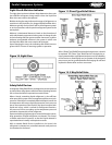
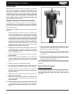
Oil Level Regulators
The AC&R adjustable oil regulators are designed to feed oil
between 1/4 and 5/8 sight glass levels. The regulator may adjust
beyond this range due to the actual oil pressure. Adjustable
regulators include an adjustment mechanism to raise or lower
the oil set point. The AC&R design eliminates the need to shut
the system down in order to adjust the oil level. The oil level may
be adjusted while the system is under pressure and running.
Adjust the oil level by removing the seal cap, the locking disk
(S-9130 & S-9190 series only), and rotating the adjustment
clockwise to lower, counter clockwise to raise the oil level.
Replace the cap and locking disk when done. Each full turn of
the adjustment mechanism moves the oil level approximately
1/16”. Oil levels on these regulators are typically factory set just
below 1/2 sight glass.
All level regulators have a operating pressure dierential range
that should not be confused with its working pressure. The
operating dierential is the dierence of pressure between
the oil feeding into the regulator and the component where
the regulator is controlling oil level. Specically, the reservoir
pressure minus the crankcase pressure. If the differential
pressure is too low for that regulator, insucient oil ow to the
compressor may result. If the dierential pressure is too high,
the regulator will overll.
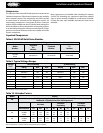
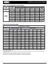
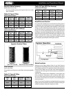
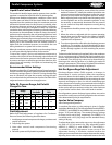
Helical
Model No.
Oil
Precharge
S-5180, S-5181 4 oz. / 11 cl
S-5182, 85, 87, 88 14 oz. / 40 cl
S-5190, 92, 94 40 oz. / 114 cl
S-5200 / S-5410 series 25 oz. / 71 cl
Conventional
Model No.
Oil
Precharge
S-5500 series 12 oz. / 34 cl
S-5600 series 30 oz. / 86 cl
S-1900, S-5700 series 25 oz. / 71 cl
S-5800 series 12 oz. / 34 cl
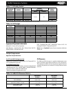
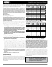
Temprite Model
No. Oil Precharge
922R, 923R 77 oz. / 2.2 L
924R , 925R 109 oz. / 3.22 L
926R, 927R 1.8 gal./ 6.7 L
928R 3.5 gal. / 13.25 L
930R 5.7 gal . / 21.25 L
Temprite Valve Adjustment
Turn in (clockwise) to increase pressure. Turn out
(counterclockwise) to decrease pressure. Approximately 7 psi
per turn. Factory set at 40 psi ±2.
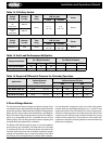
Figure 17. Temprite Oil System
Table 20. AC&R Models
Table 21. Temprite Models