


Parallel Compressor Systems Installation & Operations Manual, October 2004 31
Parallel Compressor Systems
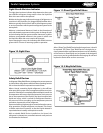
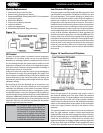
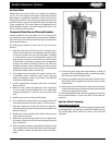
Liquid Drain Control Method
This method is ideal for large capacity systems since a smaller
regulator is required for liquid line than for discharge line.
During warm ambient temperature conditions valves A and
C will be open and Valve B will be closed. When the ambient
temperature at the condenser drops, the condenser pressure
will tend to become lower. As this pressure is reduced, when
the pressure becomes as low as its setting, Valve A will begin
to close, thus causing the refrigerant to back up inside the
condenser tubes, reducing the condensing surface and allowing
the pressure to be maintained. As Valve A closes, the receiver
pressure may be reduced by the cold entering liquid to a level
below the setting of Valve B, which will begin to open to bypass
sucient gas to maintain the receiver pressure at the set point
of Valve B. Check valve C will prevent the high pressure from
backing up to the condenser when the receiver pressure is
higher than the condenser pressure, as would be the case
during shutdown in a system with a warm receiver.
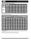
When the condenser pressure builds up to the setting of Valve
A, it will open allowing liquid to ow to the receiver.
To describe it again, during cold ambient temperature
conditions this liquid will be considerably subcooled and will
tend to lower the receiver pressure. Valve B will sense the drop
in pressure and open to admit hot gas into the drain line, thus
pressurizing and warming the liquid and maintaining the
receiver pressure.
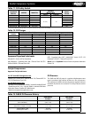
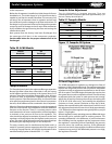
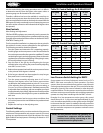
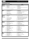
Recommended Valve Settings
Regulators ordered for a Condenser Pressure Control system for
use with common refrigerants will be furnished with the ranges
and factory settings shown in Table 29. Turning the adjusting
stem in (clockwise) will raise the set point; turning the stem
out (counterclockwise) will lower the set point. See Table 29 for
ranges and amount of pressure change per turn.
Valve
Type
Range
Factory
Set Point
Change Per
Turn
psig kg/cm
2
psig kg/cm
2
psig kg/cm
2
A4A
ARA0
D
75 to
280
5.2 to
19.7
140 9.8 53 3.7
A7A
A7A1
A72
D
75 to
280
5.3 to
19.7
120 8.4 75 5.3
A9 B
80 to
220
5.6 to
15.5
120 8.4 25 1.8
Field Adjustment
Before final field adjustment of regulators for Condenser
Pressure Control, the following should be done:
1. Install gauges to read compressor discharge, condenser and
receiver pressures.
2. Fully charge the system.
3. Have other controls and components functioning
properly.
4. Have the system as fully loaded as possible.
5. Final adjustments should be made when the outdoor
ambient is below 65°F. Ideally the ambient should be near
minimum system outdoor temperature to allow the system
pressures to drop below the regulator pressure settings.
Before adjusting make sure that all manual opening stems
on the regulators are set for automatic operation. It may
be necessary to temporarily deactivate the low pressure
cut out controls to keep the compressors running during
adjustment.
6. The regulators should be preset using information in Table
29.
7. When the valves are adjusted with the system operating,
enough time must be allowed for the system to stabilize.
Check the sight glass to make sure sufficient liquid is
supplied to the evaporators.
8. Turn the condenser fans o to allow the discharge pressure
to build up. The regulator A should be adjusted to open
when the pressure reaches the desired control point. Listen
for ow through regulator A while watching the pressure
gauge.
To determine the nal setting of regulator B, allow the condenser
fans to run long enough to subcool the liquid supplied to the
receiver. Adjust the regulator until the desired receiver pressure
is obtained. Flow through the valve can be determined by
listening at the valve for gas ow or by feeling the outlet for
change in temperature. The setting of regulator B should be at
least 10 psi lower than the setting of regulator A.
Hot Gas Bypass Regulator Adjustment
Discharge Bypass Valves (DVB) respond to changes in
downstream or suction pressure. When the evaporating
pressure is above the valve setting, the valve remains closed.
As the suction pressure drops below the valve setting, the valve
responds and begins to open. As with all modulating type
valves, the amount of opening is proportional to the change in
the variable being controlled - in this case the suction pressure.
As the suction pressure continues to drop, the valve continues
to open farther until the limit of the valve stoke is reached.
On refrigeration systems discharge bypass valves are used to
prevent the suction pressure from going below the minimum
value determined by the job requirements.
Sporlan Valve Company
Valve Setting and Adjustment
A complete discussion on valve settings is given in Sporlan
Application Bulletin 90-40. The fully adjustable models ADRS(E)-
2, ADRP(E)-3, and ADRH(E)-6 are available with two adjustment
ranges - 0/30 and 0/80 psig. The standard factory settings
for these are 20 and 60 psig, respectively. The ADRI(E)-1-1/4
is available with a 0/55 psig range and the standard factory
setting is 28 psig.
To adjust these valves, remove the cap an turn the adjustment
nut with a 5/16” hex wrench for fully adjustable models
ADRS(E)-2, ADRP(E)-3, and ADRH(E)-6. The ADRI(E)-1-
1/4 model has a 3/8” adjustment screw on top of the
adjustment housing. A clockwise rotation increases the
setting and a counterclockwise rotation decreases the setting.
Adjusting these valves can be complicated because the load
Table 29. Pressure Range, Set Point &
Charge Per Turn