


4 Part # 25000102
Installation and Operations Manual
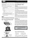
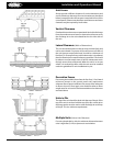
Figure 2. Vibration Pad Locations
System Warranty
This equipment is designed to operate properly and produce
the rated capacity when installed in accordance with good
refrigeration practice.
The following conditions should be adhered to when installing
this unit to maintain the manufacturers warranty:
(a) System piping must be in accordance with good
refrigeration practices
(b) Inert gas must be charged into the piping during
brazing
(c) The power supply to the unit must meet the following
conditions:
• All voltages must be +/- 10% of the n a m e p l a t e
ratings
• Phase (voltage) imbalance cannot exceed 2%
(d) All control and safety switch circuits must be properly
connected according to the wiring diagram
(e) The factory installed wiring must not be changed without
written factory approval
Rigging
Warning: Careful considerations for lifting should be made
before the unit is lifted by any means. The only part of the unit
designed to carry any of the lifting load is the welded channel
base. The unit may be lifted at the base with a forklift or by
means of cables at the four corners of the base. If cables are
used, the lifting cables should be prevented from contacting
any of the unit piping or electrical components.
Location Of Equipment - Indoor
Clearances
The parallel systems should be located so they are level and
easily serviced. The minimum suggested clearance around
the units should be 24 inches at the rear and 42 inches in the
front of panel (or as required by National or Local Codes). For
parallel system units placed end to end, 24 inches between
units is suggested.
Floor & Foundation Requirements
The total weight of a single unit will vary between 1200 pounds
and 10,000 pounds. Allowances must be made for the parallel
rack and all other equipment installed in the same area as the
parallel units. The location and installation of all equipment
should be in accordance with all local and national code
requirements.
While each unit is constructed with a welded steel base frame
adequately designed to withstand vibration, the natural
pulsating action of the interconnected motor-compressors
may cause considerable noise and vibration if the unit is not
mounted on a rm level surface and isolated from the structure
of the building.
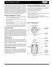
Vibration Mounts
In ordinary ground level or basement installations, all that is
necessary to assure a vibration-free installation is to place the
unit on the concrete oor with the wae-surfaced resilient pads
supplied. See Figure 2 for suggested pad locations. Mezzanine
and other installations require some special considerations.
The equivalent of 6 inch thick properly reinforced concrete
floor must be provided for mounting parallel units above
grade. It is recommended that the suggestions previously
given for rigid oor construction on above-grade installations
be closely adhered to. If this is not possible, special vibration
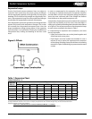
NOTE: Turn each leveling nut until the tip casting
rises 1/4” to 3/8” above the bottom
casting. MOUNT ADJUSTMENT SHOULD
NEVER EXCEED 3/4”.
Figure 1. Vibration Pad and Spring Isolator