


The value of Mask (any numeric expression can be specified) is first rounded
and then used to configure the device’s parallel response. The least
significant 3 bits (bits 0 through 2) of the expression are used to determine
which data line the device is to respond on (place its status on). Bit 3
specifies the "true" state of the parallel poll response bit of the device. A
value of 0 implies that the device’s response is 0 when its status bit message
is true.
Example The following statement configures the device at address 07 on the interface
select code 7 to respond by placing a 0 on bit 4 when its status response is
"true."
PPOLL CONFIGURE 707;4
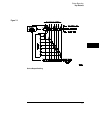
Conducting a Parallel Poll
The PPOLL (Parallel Poll) function returns a single byte containing up to 8
status bit messages for all devices on the bus capable of responding to the
poll. Each bit returned by the function corresponds to the status bit of the
device(s) configured to respond to the parallel poll (one or more devices can
respond on a single line). The PPOLL function can only be executed by the
controller. It is initiated by the simultaneous assertion of ATN and EOI.
Example Response = PPOLL(7)
Status Reporting
Conducting a Parallel Poll
7–12