


Extended Interface with Hardware Handshake
With the extended interface, both the software and the hardware can control
the data flow between the Logic Analysis System and the controller. The
Logic Analysis System uses the following connections on its RS-232-C
interface for extended interface communication:
•
Pin 5 SGND (Signal Ground)
•
Pin 3 TD (Transmit Data from Logic Analysis System)
•
Pin 2 RD (Receive Data into Logic Analysis System)
The additional lines you use depends on your controller’s implementation of
the extended hardwire interface.
•
Pin 7 RTS (Request To Send) is an output from the Logic Analysis
System which can be used to control incoming data flow.
•
Pin 8 CTS (Clear To Send) is an input to the Logic Analysis System
which controls data flow from the Logic Analysis System.
•
Pin 6 DSR (Data Set Ready) is an input to the Logic Analysis System
which controls data flow from the Logic Analysis System within two bytes.
•
Pin 1 DCD (Data Carrier Detect) is an input to the Logic Analysis
System which controls data flow from the Logic Analysis System within
two bytes.
•
Pin 4 DTR (Data Terminal Ready) is an output from the Logic Analysis
System which is enabled as long as the Logic Analysis System is turned on.
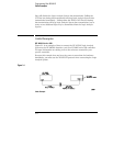
The TD (Transmit Data) line from the Logic Analysis System must connect to
the RD (Receive Data) line on the controller. Likewise, the RD line from the
Logic Analysis System must connect to the TD line on the controller.
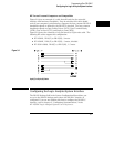
The RTS (Request To Send) is an output from the Logic Analysis System
which can be used to control incoming data flow. A true on the RTS line
allows the controller to send data and a false signals a request for the
controller to disable data transmission.
The CTS (Clear To Send), DSR (Data Set Ready), and DCD (Data Carrier
Detect) lines are inputs to the Logic Analysis System, which control data flow
from the Logic Analysis System. Internal pull-up resistors in the Logic
Analysis System assure the DCD and DSR lines remain high when they are
not connected. If DCD or DSR are connected to the controller, the controller
must keep these lines along with the CTS line high to enable the Logic
Analysis System to send data to the controller. A low on any one of these
Programming Over RS-232-C
Extended Interface with Hardware Handshake
3–5