


47
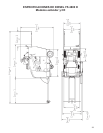
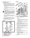
FIGURE 3-1
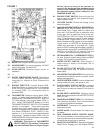
3-1A. ENGINE GEARBOX: Single Speed Model.
3-1B. WATER CONNECTION: Circulates freshwater
through gearbox to cool it. Water then ows to
the bladeguard.
3-1C. WATER DRAIN VALVE: To drain water from gear-
box: Turn Counterclockwise to open, Clockwise to
close. Drain daily to prevent corrosion or damage
due to freezing temperatures.
3-1D. HOOD LATCH: Two latches, located on the front
frame of the machine secure the ENGINE HOOD
(6E) in the lowered position. Rotate each latch 180
degrees, Counter-Clockwise, and the ENGINE
HOOD (6E) can be lifted. For European CE models,
the latch is a slotted design, and a tool, such as a
screw driver must be used to open the latch.
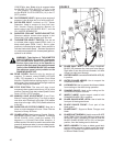
3-1E. FLANGE COVER: Guards against FLANGE con-
tact during operation. Always keep in place!
3-1F. BELT PROTECTOR SHIELD: Keep in place.
3-1G. BLADESHAFT TUBE ASSY: Sealed unit contains
bladeshaft, bearings and shaft seals.
3-1H. TIEDOWN LUGS: Used to tie the saw down
while transporting by vehicle. Not to be used to lift
the saw.
3-1I. ENGINE OIL DRAIN VALVE: Drains engine oil
without use of tools.
3-1J. BELT TENSIONING BOLTS:
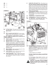
2L. BLADE GUARD SPADE LATCH: Used to hold
the blade guard in position. To remove the blade
guard, use the WIRE LANYARD (2K) to pivot the
inner BLADE GUARD SPADE LATCH to the open
position, and then lift the blade guard up and off of
the machine.
2M. REAR BOLT: Retains Blade Guard In position
(except 36” and 900mm). REAR BOLT must
be removed before removing BLADE GUARD.
Always install REAR BOLT in blade guard before
operating machine.
3-1K. HORIZONTAL CLAMPING BOLTS:
3-1L. BLADE SHAFT PULLEY:
3-1M. V-BELTS: Set of 4, 3 Groove
3-1N. GEARBOX PULLEY:
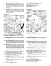
FIGURE 3-2
3-2A. ENGINE GEARBOX: Three Speed Model.
3-2B. WATER CONNECTION: Circulates freshwater
through gearbox to cool it. Water then ows to
the bladeguard.
3-2C. WATER DRAIN VALVE: To drain water from gear-
box: Turn Counterclockwise to open, Clockwise to
close. Drain daily to prevent corrosion or damage
due to freezing temperatures.
3-2D. HOOD LATCH: Two latches, located on the front
frame of the machine secure the ENGINE HOOD
(6E) in the lowered position. Rotate each latch 180
degrees, Counter-Clockwise, and the ENGINE
HOOD (6E) can be lifted. For European CE models,
the latch is a slotted design, and a tool, such as a
screw driver must be used to open the latch.
3-2E. FLANGE COVER: Guards against FLANGE con-
tact during operation. Always keep in place!
3-2F. BELT PROTECTOR SHIELD: Keep in place.
3-2G. BLADESHAFT TUBE ASSY: Sealed unit contains
bladeshaft, bearings and shaft seals.
3-2H. TIEDOWN LUGS: Used to tie the saw down
while transporting by vehicle. Not to be used to lift
the saw.
3-2I. ENGINE OIL DRAIN VALVE: Drains engine oil
without use of tools.
3-2J. BELT TENSIONING BOLTS:
3-2K. HORIZONTAL CLAMPING BOLTS:
3-2L. BLADE SHAFT PULLEY: