


52
Do not operate this saw without the GUARD
SPADE LATCH (2L) engaged and the bolt [18”-
30” (450-700mm) Blade Guards] installed.
Inspect blade guards and latches frequently.
Do not use if damaged.
To Remove A SLIP-ON GUARD:
• Using the BLADE SHAFT WRENCH (2J) remove the rear
retaining bolt [18”-30” (450-700mm) Blade Guards].
• For 14-30” (350-700mm) Blade Guards: Use the WIRE
LANYARD (2K) to open the BLADE GUARD SPADE
LATCH (2L).
• For 36” (900mm) Blade Guards: BLADE SHAFT
WRENCH (2J) is used to pivot the BLADE GUARD
SPADE LATCH (2L) to the open position.
• Lift guard off spade.
To Install A SLIP-ON GUARD:
• Lower guard onto spade until BLADE GUARD SPADE
LATCH (2L) engages.
• Install REAR BOLT (2M) [14”-30” (350-700mm) Blade
Guards] in rear of guard using the BLADE SHAFT
WRENCH (2J).
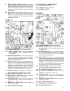
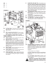
• Verify that machine is set up correctly for the DIAMOND
BLADE (2E) diameter required for the job. Check that
the correct Engine GEARBOX PULLEY (3-1N, 3-2N),
BLADE SHAFT PULLEY (3-1L, 3-2L), BLADE FLANGE
(2B & 2F), and BLADE GUARD (2H) are installed. For
machines equipped with the three-speed ENGINE
GEARBOX (3-2A), also check that the GEARBOX
SHIFT LEVER (3-2P) is in the correct gear. See
SECTION 14, “Engine / Blade Shaft / Gearbox Speed
Adjustment”, for more details.
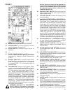
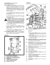
5 Fitting The Blade
(See Figures 1 and 2)
• Set ENGINE START SWITCH (1H) to “1” position.
• Raise Machine to a high position using the
TOGGLE SWITCH (1P) on the SPEED CONTROL
LEVER (1O).
• Set the ENGINE START SWITCH (1H) to the “0”
(OFF) position.
• Loosen Bolt on BLADE GUARD NOSE LATCH (2G).
• Raise Front Half of BLADE GUARD (2H).
• Loosen Bladeshaft Bolt (2A) Remove OUTER
FLANGE (2B).
• Fit DIAMOND BLADE (2E) to OUTER FLANGE
ARBOR (2C).
• Install OUTER FLANGE (2B) into the BLADE SHAFT
(2I) making sure that the LOCKING PIN (2D) passes
through the DIAMOND BLADE (2E) and into the INNER
FLANGE (2F).
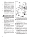
Note the direction of rotation of the blade.
The direction of rotation is shown by an
arrow on both the DIAMOND BLADE (2E)
and the BLADE GUARD (2H). Make sure
that the contact surfaces on the DIAMOND
BLADE (2E), INNER & OUTER FLANGES
(2B & 2F) and OUTER FLANGE ARBOR (2C)
are clean.
• Rotate OUTER FLANGE (2B) and DIAMOND
BLADE (2E) in the opposite direction of blade rotation
to remove backlash.
• Install and tighten Blade Shaft Bolt (2A) while rmly
holding the DIAMOND BLADE (2E). Tighten using the
BLADE SHAFT WRENCH (2J) provided.
• Lower front half of BLADE GUARD (2H) and tighten the
Bolt on the BLADE GUARD NOSE LATCH (2G).
The Blade Shaft Bolt (2A) on the Right Hand
side has Left Hand threads. The Blade Shaft
Bolt (2A) on the Left Hand side has Right
Hand threads.
Slip-On blade guards are provided with a
safety BLADE GUARD SPADE LATCH (2L)
which engages the support spade and a
REAR BOLT (2M) [18”-30” (450-700mm) Blade
Guards], to retain the rear of the guard.
6 Starting The Saw
(See Figures 1, 2 and 5)
Always pay extreme care and attention to the
preparation of the machine before starting.
Remove all wrenches and tools from the oor
and the machine.
Always keep blade guard, belt guards and
fan guards in place.
• Follow all operating instructions and warnings in this
manual and on the machine.
• Close the WATER VALVE (1T).
• Mark the surface to be cut by drawing a line where the
cut is to be made.
• Pull out Handle Bars (1B) to desired length and tighten
Knobs (1A).
• Lower the Front Guide (6D) and align the Front Guide
(6D), Rear Guide (6F) and DIAMOND BLADE (2E) with
the line on the surface.
• To start the saw when no water pressure is present, set
the WATER SAFETY SWITCH (1L) to “0” (OFF).
• Set SPEED CONTROL LEVER (1O) to the STOP
POSITION (1BB). Saw will not start unless the SPEED
CONTROL LEVER (1O) is in the STOP POSITION
(1BB). Check to be certain the TRANSMISSION
BYPASS VALVE (6J, Front Pivot Models Only) is closed
in the down position.
• Set the BLADE CLUTCH SWITCH (1V) (if equipped)
to “0” (OFF).