


49
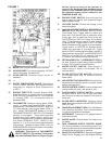
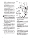
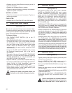
FIGURE 6
6A. LIFTING BAIL: The saw can be lifted only
from this point. Do NOT lift the saw from any
other location.
6B. ----
6C. BELT GUARDS AND SHIELDS: Protects engine,
guards, drives, and cooling fan. Do not remove
during operation, or when engine is running!
DO NOT OPERATE ENGINE WITH SHIELDS OR
GUARDS REMOVED!
6D. FRONT GUIDE: Use to locate the path of the
diamond blade on the cutting line.
6E. ENGINE HOOD: Protects engine, cooling fan,
beltdrives and pulleys. The ENGINE HOOD is
a guard, and must be latched in the lowered
position before starting engine and operating saw.
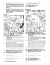
Open ENGINE HOOD by rotating the two HOOD
LATCHES (3-1D, 3-2D) Counter-Clockwise 180
degrees. Swing upward and secure using HOOD
SUPPORT (6H).
6F. REAR GUIDE: Use to locate the path of the
diamond blade on the cutting line.
6G. HANDLEBARS: Used to maneuver the saw. Not
to be used to lift the saw. (Same as 1B)
6H. HOOD SUPPORT: Latch to secure the hood
in the open position. Always lower and secure
the hood before starting the engine or operating
the machine.
5M. ----
5N. ----
5O. ----
5P. ----
6I. RADIATOR COOLANT FILL: Fill radiator from
this point. Warning: Avoid injury! Built-up pressure
may cause explosive release of coolant when the
radiator cap is removed. Shut off the engine and
allow to cool. Do not remove the cap unless the
radiator and the engine are cool enough to touch
with bare hands. Slowly loosen the cap to the rst
stop to release all pressure. Then remove the cap.
Replace cap if damaged.
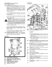
6J. TRANSMISSION BYPASS VALVE (Front Pivot
Model Only): Turn counter clockwise to open.
Turn clockwise to close. Open to allow pushing of
concrete saw.
6K. HYDROSTATIC TRANSMISSION PUMP.
6L. ALTERNATOR: See Yanmar for replacements.
6M. ALTERNATOR / WATERPUMP BELT: Self
Tensioning. See Yanmar for replacements.
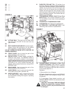
FIGURE 7
7A. PARKING BRAKE (CE Models or Rear Pivot
models-If Equipped): Holds machine in parked
position on a slope of 10 degrees or less. PARKING
BRAKE (7A) located on left hand side of machine,
at rear wheel (See FIG 7).
Operation:
1) Stop machine, turn off engine.
2) To apply: Stand behind machine, push PARKING
BRAKE LEVER (7A) forward (Toward front
of machine).
3) To disengage: Stand behind machine, pull
PARKING BRAKE LEVER (7A) backwards toward
rear of machine.
CAUTION: Disengage PARKING BRAKE
LEVER (7A) before fully engaging SPEED
CONTROL LEVER (7B), else machine could
be damaged.