


143
Chapter 9 - Appendix
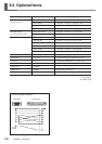
9-6. Specifications
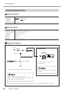
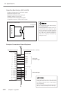
Expansion Connector 2
This connector is for input and output with external equipment. It is used in combination with the teaching feature. It
makes it possible to control the machine using signals from an external device and to send signals from the machine to an
external device with specified timing. For information about how to perform control using expansion connector 2, refer
to "Chapter 4 The Teaching Feature."
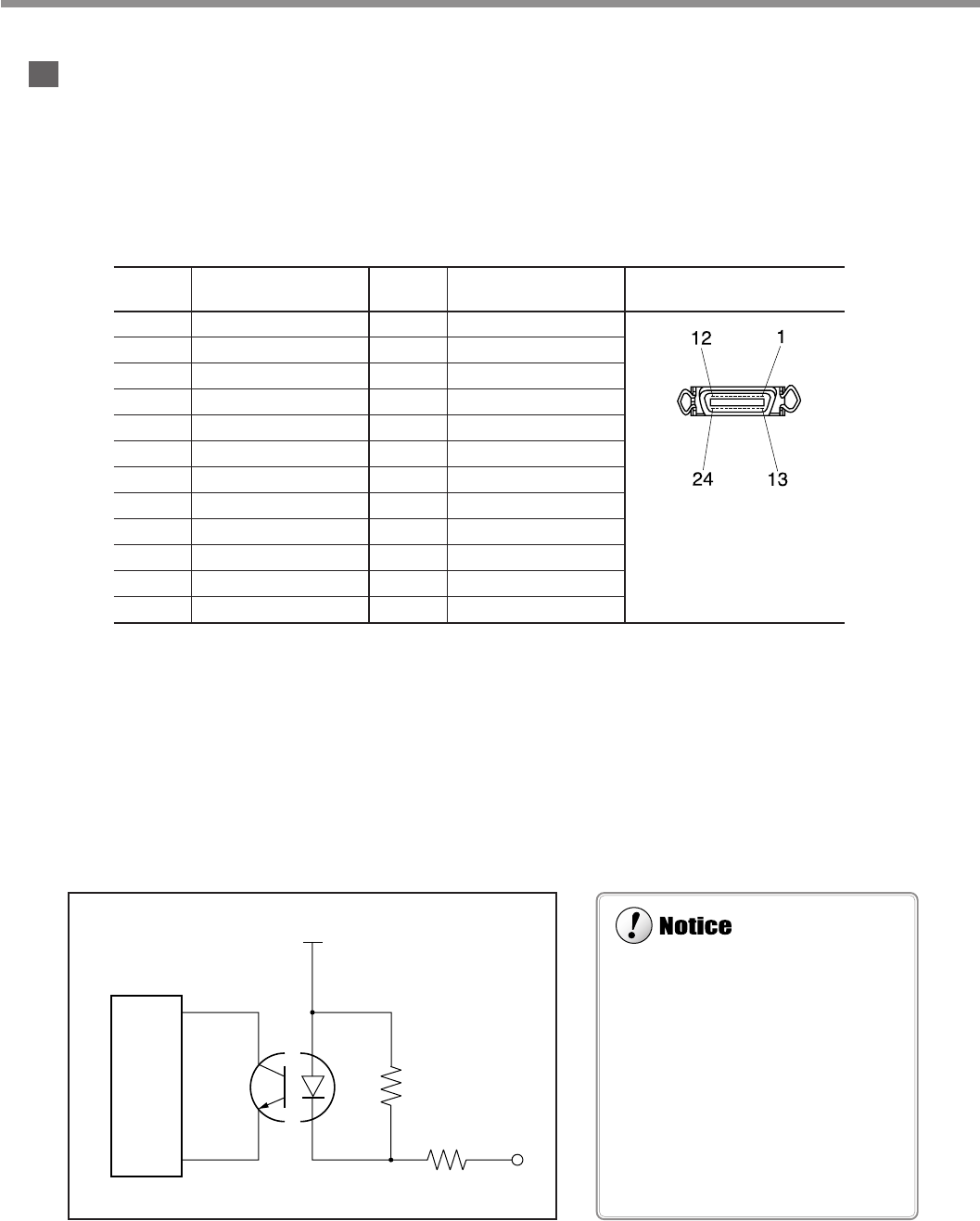
Pin Connections
* No responsible is assumed for effects to which any equipment connected to this external output connector
is subjected.
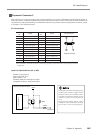
Input Port Specifications (IN1 to IN8)
Number of input ports: 8
Input voltage: DC 24 V
Input current: 7 mA
Insulation method: Isolated photocoupler
Compatible connector: Sink-mode output
Internal circuit
+24V
560Ω
3.3KΩ
Input port
Internal Circuit Schematic
The outputs connected to the input ports are
assumed to be contactless outputs such as
transistors. When you are making connec-
tions that use mechanical contact (such as
switches or relays), use microcurrent de-
vices.
Ensure that the leakage current when a
contactless circuit connected to the input
ports is off is 1 mA or less per input port.
Terminal
No.
1
2
3
4
5
6
7
8
9
10
11
12
Terminal
No.
13
14
15
16
17
18
19
20
21
22
23
24
Signal
PW
PW
IN 8 (Input port 8)
IN 7 (Input port 7)
IN 6 (Input port 6)
IN 5 (Input port 5)
IN 4 (Input port 4)
IN 3 (Input port 3)
IN 2 (Input port 2)
IN 1 (Input port 1)
NC
NC
Signal
PG
PG
OUT 8 (Output port 8)
OUT 7 (Output port 7)
OUT 6 (Output port 6)
OUT 5 (Output port 5)
OUT 4 (Output port 4)
OUT 3 (Output port 3)
OUT 2 (Output port 2)
OUT 1 (Output port 1)
NC
NC
Pin connections
Amphenol 24 pin