


74
Chapter 5 - The Teaching Feature
5-2. Basic Steps for Creating and Executing a Sequence
Step 2 Create the Sequence
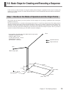
Now let's actually create the sequence. First carry out operations without loading a workpiece. We'll assume that the Z0
position is set at the surface of the workpiece.
Example of Sequence Creation
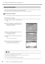
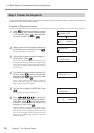
1
Press several times to display the screen
shown at right, then move the blinking cursor
to [TEACHING]. Press . Move the blink-
ing cursor to [EDIT], then press .
2
Specify creation of a new sequence. Make sure
the blinking cursor is at [Yes], then press .
The sequence editing screen appears.
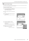
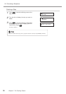
3
Turn the dial to make the display change to [1
MOVE-LIMIT]. Press .
You have now finished entering the commands to move
the spindle to the machine origin point at the highest speed
as the first step. When you finish making the entries for
the first step, the display changes to the input screen for
the second step.
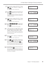
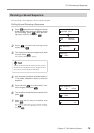
4
Turn the dial to make the display change to [10
SP OFF]. Press , then turn the dial to dis-
play [ON]. Press again, then turn the dial
to display [100]. Press .
Now you have entered the commands for rotating the
spindle. [100] means rotation at 10,000 rpm. Now the
input screen for the third step appears.
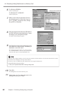
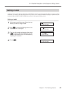
5
Turn the dial to display [3 MOVE-ZM]. Press
.
The screen changes to the coordinate view.
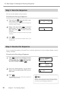
6
Press to move the X
and Y axes to the first cutting point (X 2000, Y
1000). Next, press to move the Z axis to
a location 1 millimeter from the surface of the
workpiece (Z 100). Press .
Check the displayed coordinates as you perform move-
ment. Now you have entered the commands for moving
the X and Y axes to the specified position, then lowering
the Z axis at the highest speed to a position close to the
surface of the workpiece. Next, the input screen for the
fourth step appears.
1:
< 1 MOVE-LIMIT >
2:
< 10 SP ON 100 >
3:
3 MOVE-ZM
X 2000 Y 1000
Z 100 8000RPM
I/O OTHERS
TEACHING SELF
RUN DELETE
EDIT SETTING
Edit New File ?
Yes No