


75
Chapter 5 - The Teaching Feature
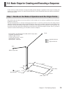
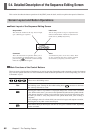
5-2. Basic Steps for Creating and Executing a Sequence
7
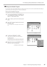
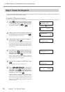
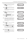
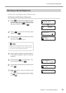
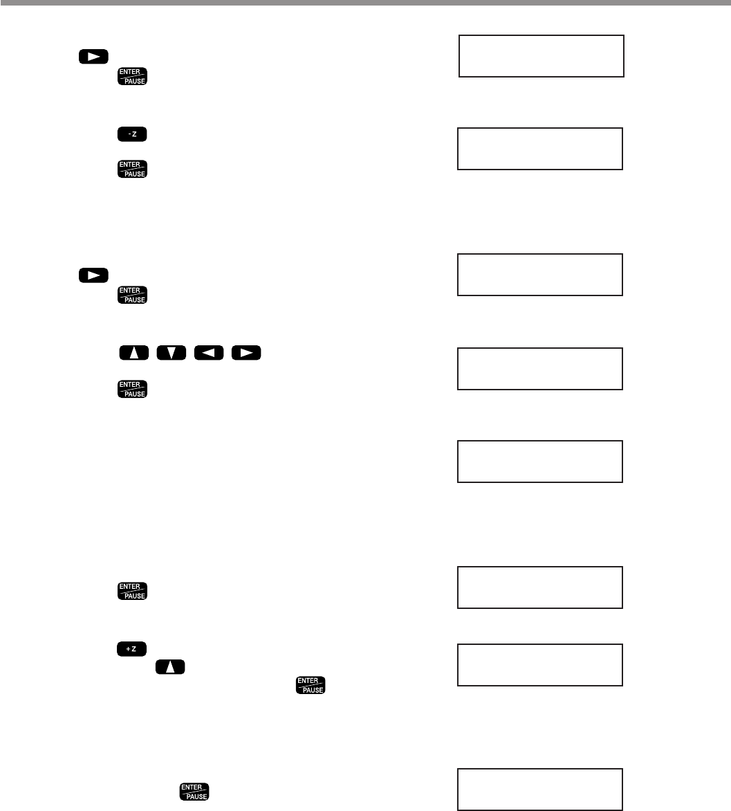
Turn the dial to display [8 CUT-3 2]. Press
, then turn the dial to display [3].
Press .
The screen changes to the coordinate view.
8
Press to move the Z axis to where it cuts
into the workpiece by 0.2 mm (Z -20).
Press .
Now you have entered the commands for cutting into the
workpiece at a feed rate of 3 mm/s. Next, the input screen
for the fifth step appears.
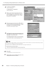
9
Turn the dial to display [8 CUT-3 2]. Press
, then turn the dial to display [15].
Press .
The screen changes to the coordinate view.
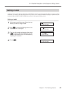
10
Press to move the X
and Y axes to the (X 7000, Y 1000) point.
Press .
Next, the input screen for the sixth step appears.
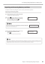
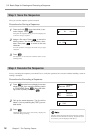
11
In the same way as for steps 9 and 10, input
the commands to move to (X 7000, Y 4000), to
(X 2000, Y 4000), and to (X 2000, Y 1000).
Now you have entered the commands for cutting a quad-
rilateral at a feed rate of 15 mm/s. Next, the input screen
for the ninth step appears.
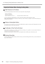
12
Turn the dial to display [3 MOVE-ZM].
Press .
The screen changes to the coordinate view.
13
Press to raise the Z axis to its upper limit.
Then press to move the Y axis all the
way to the back of the table. Press .
Now you have entered the commands for raising the Z
axis to the upper limit, then moving the spindle out of
the way. Next, the input screen for the tenth step appears.
14
Turn the dial to make the display change to [10
SP OFF]. Press .
Now you have entered the command for stopping rota-
tion of the spindle. The input screen for the eleventh step
then appears, but the procedure is finished. The final step
must always be [22 FINISH].
4:
8 CUT-3 3
X 2000 Y 1000
Z -20 8000RPM
5:
8 CUT-3 15
X 7000 Y 1000
Z -20 8000RPM
6:
8 CUT-3 15
9:
3 MOVE-ZM
X 2000 Y 40700
Z 4128 8000RPM
10:
< 10 SP OFF >