


144
Chapter 9 - Appendix
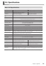
9-6. Specifications
Output Port Specifications (OUT1 to OUT8)
Number of output ports: 8 (sink-mode output)
Rated load voltage: DC 24 V
Maximum load current: 20 mA per port
Leakage current: 0.1 mA or less
Insulation method: Isolated photocoupler
Compatible connector: External-device input
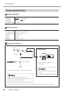
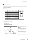
Example of Connection to External Equipment
Do not apply loads greater than the forego-
ing to the output ports.
The output ports are assumed to be con-
nected to loads such as transistors. When
they are connected to an inductive load such
as a relay, be sure to connect a protect di-
ode to the coil to absorb counterelectro-
motive force. Improper connection may
damage the circuit.
Internal circuit
Output port
Internal Circuit Schematic
Reversing the polarity of the power source may
damage the circuit. Be sure to check this before
you switch on the power. Also, do not attempt to
test the insulation.
Protect unused and never-connected (NC) pins so
that they do not accidentally short to other pins.
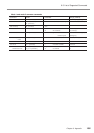
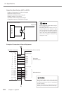
(No.)
1
2
3
4
5
6
7
8
9
10
11
12
13
14
15
16
17
18
19
20
21
22
23
24
(Signal)
PW
PW
IN 8
IN 7
IN 6
IN 5
IN 4
IN 3
IN 2
IN 1
NC
NC
PG
PG
OUT 8
OUT 7
OUT 6
OUT 5
OUT 4
OUT 3
OUT 2
OUT 1
PG
PG
Common output
OUT 8
OUT 7
OUT 6
OUT 5
OUT 4
OUT 3
OUT 2
OUT 1
Common input
IN 8
IN 7
IN 6
IN 5
IN 4
IN 3
IN 2
IN 1
0V
Sink-mode
transistor output
Sink-mode input
+24V
Expansion Connector 2 External Equipment (PCL or the like)