


V300-PRO
INSTALLATION
A-4 A-4
Return to Section TOC Return to Section TOC Return to Section TOC Return to Section TOC
Return to Master TOC Return to Master TOC Return to Master TOC Return to Master TOC
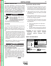
POWER INPUT CONNECTION
Connect terminal marked to earth ground per any
existing local or national electrical codes.
Single Phase Input
Connect the supply lines to the upper and lower termi-
nals of the line switch. Torque to 27.5in.-lbs.(3.0 Nm).
Do not use center terminal of the line switch.
Three Phase Input
Connect the supply lines to the line switch. Torque to
27.5in.-lbs.(3.0 Nm).
Install in accordance with all local and national electric
codes.
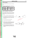
The V300-PRO is supplied with one cord connector to
provide strain relief for the input power cord. It is
designed for a cord diameter of .310-1.070” (7.9 -
27.2mm). The jacketed portion of the cord must go
through the connector before tightening the connector
screws.
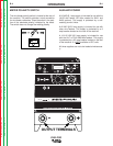
CONNECTION OF WIRE FEEDERS TO
THE INVERTEC
LN-25 Connection Instructions
1. Turn the Invertec power switch “off”.
2. Connect the electrode cable to the output terminal
of polarity required by electrode. Connect the work
lead to the other terminal.
3. LN-25 with remote control options K431 and K432.
Use K876 adapter with K432 cable or modify K432
cable with K867 universal adapter plug. See con-
nection diagram S19899 and S19309 or S19405 in
Operator’s Mamual.
4. Place the local-remote switch in the “remote” posi-
tion if output control is desired at the wire feeder
rather than the Invertec. (LN-25 must have K431
and K432 options for remote output control opera-
tion).
LN-7 Connection Instructions (not applicable to
IEC machines with only 42V Aux.).
1. Turn the Invertec power switch “off”.
2. Connect the K480 or K1818-10 control cable from
the LN-7 to the Invertec control cable connector.
The control cable connector is located at the rear
of the Invertec.
3. Connect the electrode cable to the output terminal
of polarity required by electrode. Connect the work
lead to the other terminal.
4. Place the local-remote switch in the “local” position
to allow output control at the Invertec. (K864
remote control adapter and K857 remote control
are required for remote output control. See con-
nection diagram S19901.
5. Set the meter polarity switch on the rear of the
Invertec to coincide with wire feeder polarity used.
The wire feeder will now display the welding volt-
age.
6. If a K480 or K1818-10 is not available, see con-
nection diagram S19404 for modification of K291
or K404 LN-7 input cable with K867 universal
adapter plug..
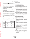
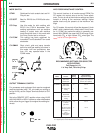
Recommended Fuse Sizes Based On The U.S.
National Electrical Code And Maximum Machine
Outputs
Fuse Size in Amps
Input Volts
(1)
(Time Delay Fuses)
208 60
3 phase 230 60
50/60 Hz 460 40
575 25
1 phase 208 85
50/60 Hz 230 80
460 50
(1)
Input voltage must be within ±10% of rated value.