


B300-PRO
TROUBLESHOOTING & REPAIR
TEST PROCEDURE
1. Turn main power OFF.
2. Perform Input Filter Capacitor Dis-charge proce-
dure detailed in Mainten-ance section..
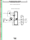
3. Connect a shorting conductor across terminals 14
and 53 of Protection Board.
4. Set an ohmmeter to X1000 range and place probes
on terminals 9 (+) and 12 (-) of one Switch Board.
The meter will show the Capacitors charging up
and may take a minute or so to stabilize. The final
meter reading should not exceed 8600 ohms (8.6
on the scale).
5. Test the other Switch Board the same way.
NOTE: Repeat the Input Filter Capacitor Dis-charge
procedure.
6. Remove the shorting conductor set up in step 3.
7. Install 5-amp fuses in the input supply fuse holders.
NOTE: These fuses should be installed to protect
against excessive current flow caused by a short
circuit during the procedure.
8. Turn on the machine.
9. With the output free of a load, check the open cir-
cuit voltages of the output.
10. Connect the machine for 440- or 575-volt opera-
tion.
11.With the output free of a load, check open circuit
voltages of the output. Voltage should be 70 VDC.
12. Remove the 5-amp fuse from the input supply fuse
holders.
13. Install 20-amp fuses and test under load.
NOTE: A resistive-type grid load bank is recom-
mended.
14. Perform Retest After Repair.
F-58 F-58
Return to Section TOC Return to Section TOC Return to Section TOC Return to Section TOC
Return to Master TOC Return to Master TOC Return to Master TOC Return to Master TOC
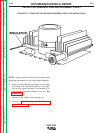
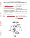
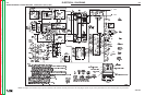
TEST AFTER SWITCH BOARD OR CAPACITOR REPLACEMENT (cont.)
FIGURE F.30 - PLACEMENT OF SHORTING JUMPER