


V300-PRO
TROUBLESHOOTING & REPAIR
TEST PROCEDURE
1. Perform Input Filter Capacitor Discharge
Procedure detailed in this section.
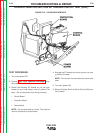
2. Remove front panel from machine to access Control
Board.
3. Arrange wires so there is ample room to work on
the board.
4. Turn main power ON.
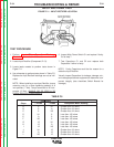
5. Test for 15 VDC between leads 302 and 275D.
a. If 15 VDC is present, test is OK. Go to step 6.
b. If 15 VDC is not present, check Power Board
and leads 302 and 275D for continuity and wire
breakage.
F-36 F-36
Return to Section TOC Return to Section TOC Return to Section TOC Return to Section TOC
Return to Master TOC Return to Master TOC Return to Master TOC Return to Master TOC
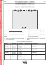
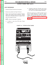
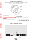
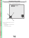
OVERCURRENT PROTECTION CURRENT TRIGGER TEST (cont.)
FIGURE F.12 - GETTING ACCESS TO CONTROL BOARD
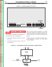
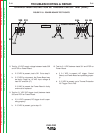
G2527
CONTROL
302
275D
J5
J1 J2
J4
J3
FIGURE F.13 - CONTROL BOARD TEST POINTS