


V300-PRO
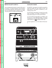
THEORY OF OPERATION
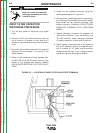
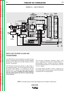
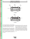
INPUT LINE VOLTAGE & AUXILIARY
TRANSFORMER
The V300-PRO can be connected for a variety of three
phase or single phase input voltages. Power is applied
through the Line Switch to the Input Rectifier and the
Auxiliary Transformer.
The Reconnect Panel has switches to select high or
low operating voltage. The “A” lead must then be set for
the proper input voltage. It is important to set the
switches and “A” lead to the proper positions before
applying input power. Changing the switch position
with the power applied will result in major damage
to the machine
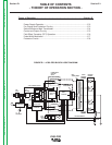
The auxiliary transformer provides 18v.a.c. and
24v.a.c. supplies to the Control and Power Boards. It
also provides 115v.a.c., 42v.a.c. and 24v.a.c. supplies
to the wirefeeder amphenol. (CE machines do not have
115v.a.c. supply)
The Power Board provides a 15v.d.c. supply to the
Control Board and a 24v.d.c.supply to the Driver Board
to operate the Pre-charge Relays.
E-2 E-2
Return to Section TOC Return to Section TOC Return to Section TOC Return to Section TOC
Return to Master TOC Return to Master TOC Return to Master TOC Return to Master TOC
1ø OR 3ø DETETCTION (H5)
LINE
SWITCH
INPUT
RECTIFIER
AC1
AC2
AC3
A-LEAD
AUXILIARY
TRANSFORMER
TO
WIREFEEDER
18VAC
24VAC
POWERBOARD
24VDC
PULSE
TRAIN
DRIVER
BOARD
PRE-CHARGE
PRE-CHARGE
2ND STEP PWM
1ST STEP PWM VOLTAGE
15VDC-CONTROL BOARD FUNCTION VOLTAGE
24VAC-THERMOSTATS-GUN TRIGGERING
LOCAL
REMOTE
METER
MODE
POT
POT
PROTECTION
BOARD
<1 VDC
RIGHT SWITCH BOARD
FET MODULES
CAP
FET MODULES
FAN
1
2
3
CONTROL
BOARD
Y-Y FEEDBACK
CR1
CR2
3A
POWER SWITCH
SECTIONS
20KHZ
LEFT SWITCH BOARD
FET MODULES
CAP
FET MODULES
CURRENT
TRANSFORMER
MAIN
TRANSFORMER
CHOKE
RECTIFIER
HEATSINK
BOTTOM
1 DIODE
5 DIODES
5 DIODES
TOP
TOP
1 DIODE
CHOKE
CHOKE
SHUNT
CURRENT FEEDBACK-PROTECTION
VOLTA GE FEEDBACK
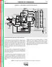
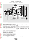
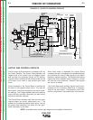
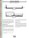
FIGURE E-2 --- INPUT CIRCUITS
NOTE: Unshaded areas of block logic diagram are the subject of discussion