


V300-PRO
THEORY OF OPERATION
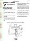
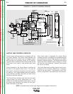
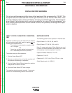
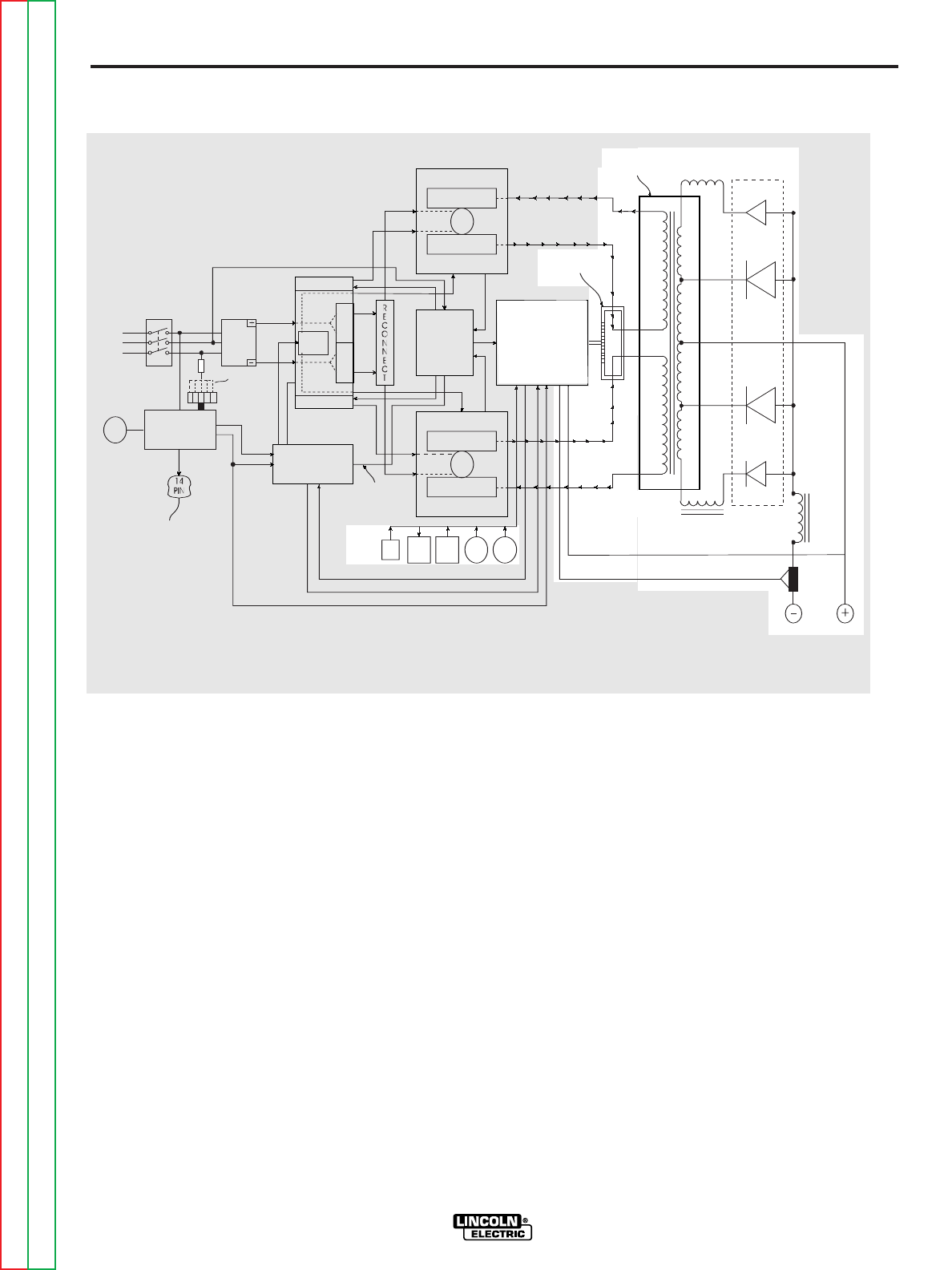
OUTPUT AND CONTROL CIRCUITS
The AC output of the transformer is changed to DC by
the Output Rectifier. The Output Choke between the
negative side of the rectifier and the negative output
stud provides the necessary filtering for DC welding.
The two smaller chokes and their series diodes are the
OCV boost circuit used to help provide good weld
starts.
Current feedback to the Control Board is provided by
the shunt in the negative output circuit. It is used for
weld control, overcurrent protection and actual amme-
ter readings. The Voltage feedback lead at the positive
output stud also provides information for weld control
and actual voltmeter readings.
The Control Board monitors input from the front panel
controls (output, arc control, mode switch, etc..). The
software on the board processes these inputs, sets up
the proper weld information and sends the “set” para-
meter information to the meter.
When weld output is requested, the Control Board
compares the input information to the feedback signals
and provides the correct PWM signals to the Switch
Boards for optimum welding. The Mode Switch setting
determines which feedback signal (voltage or current)
will have the most relevance. However, both signals
are used in all modes.
The Control Board also monitors signals from the ther-
mostats and the Protection Board and if necessary,
shuts off the weld output. The protection circuit infor-
mation is discussed in more detail later in this section.
E-5 E-5
Return to Section TOC Return to Section TOC Return to Section TOC Return to Section TOC
Return to Master TOC Return to Master TOC Return to Master TOC Return to Master TOC
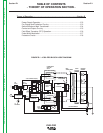
1˘ OR 3˘ DETETCTION (H5)
LINE
SWITCH
INPUT
RECTIFIER
AC1
AC2
AC3
A-LEAD
AUXILIARY
TRANSFORMER
TO
WIREFEEDER
18VAC
24VAC
POWERBOARD
24VDC
PRE-CHARGE
2ND STEP PWM
1ST STEP PWM VOLTAGE
15VDC-CONTROL BOARD FUNCTION VOLTAGE
24VAC-THERMOSTATS-GUN TRIGGERING
<1 VDC
FAN
1
2
3
3A
POWER SWITCH
SECTIONS
20KHZ
PULSE
TRAIN
DRIVER
BOARD
PRE-CHARGE
CR1
CR2
PROTECTION
BOARD
TOP
TOP
LEFT SWITCH BOARD
FET MODULES
CAP
FET MODULES
MAIN
TRANSFORMER
RIGHT SWITCH BOARD
FET MODULES
CAP
FET MODULES
BOTTOM
1 DIODE
5 DIODES
5 DIODES
1 DIODE
CHOKE
SHUNT
RECTIFIER
HEATSINK
CHOKE
CHOKE
CURRENT
TRANSFORMER
VOLTA GE FEEDBACK
CURRENT FEEDBACK-PROTECTION
CONTROL
BOARD
Y-Y FEEDBACK
LOCAL
REMOTE
METER
MODE
POT
POT
FIGURE E-5 --OUTPUT & CONTROL CIRCUITS
NOTE: Unshaded areas of block logic diagram are the subject of discussion