


V300-PRO
TROUBLESHOOTING & REPAIR
F-22 F-22
Return to Section TOC Return to Section TOC Return to Section TOC Return to Section TOC
Return to Master TOC Return to Master TOC Return to Master TOC Return to Master TOC
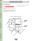
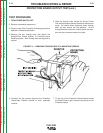
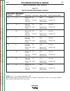
STATIC CAPACITOR TEST
TEST PROCEDURE:
1. With Output Terminal Switch S4 in REMOTE (OFF)
position, turn Power Switch ON.
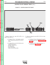
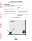
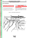
2. Test VDC across terminals 9 and 12 of one Switch
Board (see Fig F.7). Repeat the test for the other
Switch Board. See Table F.1 in this procedure for
expected voltage readings.
NOTE: For 575 VAC only machines, compare volt-
age across 9A and 13 and 13 and 12A; then 9B and
15 and 15 and 12B.
3. Record VDC measured for each Switch Board and
determine the difference in VDC.
NOTE: The following measurements should result
based on VAC input.
TABLE F.1 — EXPECTED VOLTAGE READINGS.
a. If less than 25 VDC difference is measured between
the Switch Boards, then capacior balance is OK.
• This indicates that Capacitors C1 and C2,
Resistors R1 and R9 are OK.
• (575 VAC only machines — Capacitors C1,
C2, C14, and C15; Resistors R1 and R9 are
OK.)
Go to Dynamic Capacitor Balance Test.
b. If more than 25 VDC difference is measured
between the Switch Boards, test each of the fol-
lowing components:
• Capacitors C1 and C2 and Resistors R1 and
R9.
• (575 VAC only machines —Capacitors C1,
C2, C14, and C15; and Resistors R1 and
R9.)
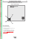
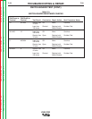
DYNAMIC CAPACITOR TEST
TEST PROCEDURE:
1. Move Output Terminal Switch S4 to ON position.
Adjust the output control to the minimum setting.
Place the mode control at the SMAW (soft) position.
2. Test VDC across terminals 9 and 12 of one Switch
Board (see Fig. F.7). Repeat the test for the other
Switch Board. See Table F.1 for expected voltages
NOTE: For 575 VAC ONLY, compare voltage
across 9A and 13 and 13 and 12A; then 9B and 15
and 15 and 12B.
3. Record VDC measured for each Switch Board and
determine the difference in VDC. (See Table F1).
a. If less than 15 VDC difference is measured
between the Switch Boards, test is OK.
b. If more than 15 VDC difference is measured
between the Switch Boards, the Power Board
or Switch Board is damaged. See SWITCH
BOARD test and POWER BOARD test.
VDC at Switch
Board Terminals
should be
If VAC Input is: approximately:
575VAC 407 VDC
460 VAC 325 VDC
440 VAC 311 VDC
415 VAC 293 VDC
380 VAC 269 VDC
CAPACITOR BALANCE TEST (cont.)