


V300-PRO
TROUBLESHOOTING & REPAIR
TEST PROCEDURE
1. Perform Input Filter Capacitor Discharge
Procedure as detailed in this section.
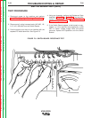
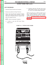
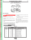
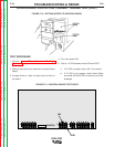
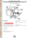
2. Locate Input Rectifier (Component D-13).
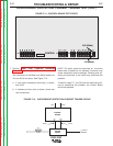
3. Locate leads needed to perform tests shown in
Figure F.11.
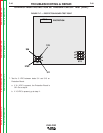
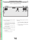
4. Use ohmmeter to perform tests shown in Table F.5.
Replace the Inpit Rectiferif readings are not as indi-
cated
NOTE: When installing a new Input Rectifier, torque
mounting nuts (in a cross tightening pattern) to 6
inch-pounds (.7 Nm). Torque terminals to 26 inch-
pounds (3 Nm). ALWAYS GO TO STEP 6 TO
CHECK RELATED COMPONENTS.
6. Inspect Main Power Switch S1 and replace if faulty.
Go to step 7.
7. Test Capacitors C1 and C2 and replace both
Capacitors if either is faulty.
NOTE: Faulty Capacitors could be the reason for a
defective Input Rectifier.
Visually inspect Capacitors for leakage, damage, etc.,
and use appropriate test equipment to determine com-
ponent integrity (also check/test Switch Boards for
damage).
F-34 F-34
Return to Section TOC Return to Section TOC Return to Section TOC Return to Section TOC
Return to Master TOC Return to Master TOC Return to Master TOC Return to Master TOC
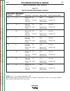
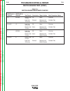
INPUT RECTIFIER TEST
Test Points
Steps + Probe – Probe Acceptable Meter Reading
A9H1 Greater than 1K ohms
B9AGreater than 1K ohms
C9H5 Greater than 1K ohms
DH19Less than 100 ohms
EA9Less than 100 ohms
FH59Less than 100 ohms
G12H1Less than 100 ohms
H12ALess than 100 ohms
I12H5Less than 100 ohms
JH112Greater than 1K ohms
KA12 Greater than 1K ohms
LH512Greater than 1K ohms
TABLE F.5
FIGURE F.11 - INPUT RECTIFIER LOCATION