


V300-PRO
TROUBLESHOOTING & REPAIR
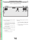
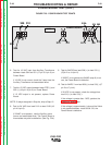
6. Test for 18 VAC input from Auxiliary Transformer
between leads 504 and 501 (J7-pin 5 & pin 6) on
Power Board.
If 18 VAC is not correct, check the 3 amp fuse, the
Auxiliary Transformer and associated wires.
7. Test for 15 VDC output between leads 275D (-) and
302 (+) (J6-pin1 & pin 6) on Power Board.
If 15 VDC output is not present, replace Power
Board.
NOTE: If relays energized in Step 4a, skip to Step 10.
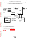
8. Test for 24 VAC from lead 211A to lead 212A (J6-
pin 4 & pin 9).
If 24VAC is not present, test the Auxiliary trans
former and associated wires. The Control Board or
thermostats may also be defective. (See Fig. F.24).
9. Test for 24VDCfrom lead 309 (+) to lead 313 (-)
(J7pin 2 to J14 pin 2).
If 24VDC is not present but 24VAC (step 8) is cor
rect, the Power Board is defective.
10. Test for 24VDC from lead 309(+) to lead 310(-) (J7
pin 2 to J7 pin 4).
If 24 VDC is not present, check the voltage from
lead 311(+) to lead 313(-).
If the voltage is greater than 1VDC, perform the
Protection Board test.
If the voltage is approximately 1vdc and the 24vdc
is not present between leads 309 & 310, the
Power Board is defective
F-49 F-49
Return to Section TOC Return to Section TOC Return to Section TOC Return to Section TOC
Return to Master TOC Return to Master TOC Return to Master TOC Return to Master TOC
POWER BOARD TEST (cont.)
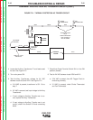
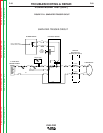
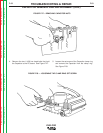
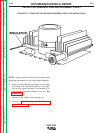
FIGURE F.23 - POWER BOARD TEST POINTS
POWER BOARD
J6
J7
J14
L8033
501
313
311
309 310
504
302
305
301
212A
211A
275D