


V300-IPRO
TROUBLESHOOTING & REPAIR
F-26 F-26
Return to Section TOC Return to Section TOC Return to Section TOC Return to Section TOC
Return to Master TOC Return to Master TOC Return to Master TOC Return to Master TOC
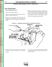
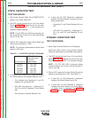
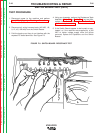
SWITCH BOARD TEST (cont.)
TEST PROCEDURE
1. Disconnect power to the machine and perform
Input Filter Capacitor Discharge Procedure as
described in Section F.
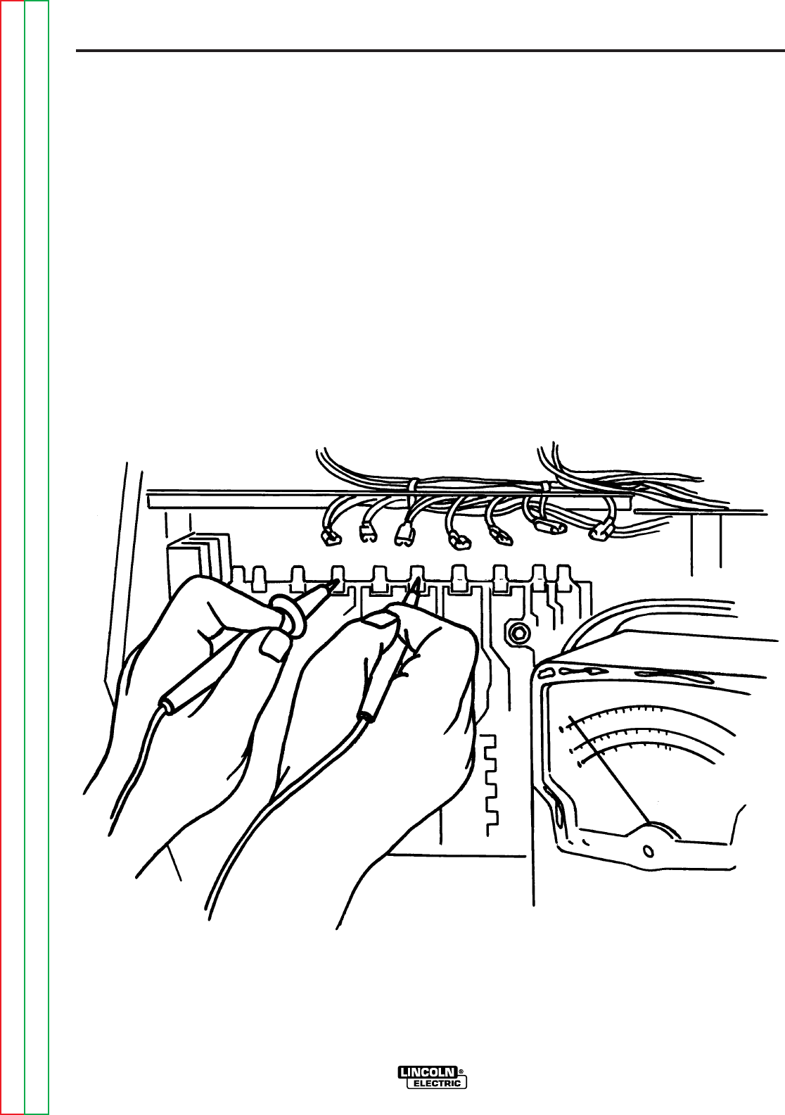
2. Disconnect all wiring harness leads (401/403, 1/8,
9, 12, 4/5, 402/404) from the Switch Boards.
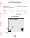
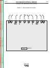
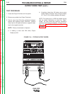
3. Fold the leads up so they do not interfere with the
exposed PC board terminals. See Figure F.8.
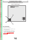
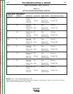
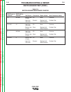
4. Using an ohmmeter, perform the Resistance Tests
detailed in Table F.2 and Table F.3. If any test fails,
replace both Switch Boards. See Switch Board
replacement procedure.
5. If the Switch Boards appear to be burned or over-
heated, or if the machine was supplied by a 380
VAC or higher voltage supply when the failure
occurred, replace the Capacitors and the Switch
Boards.
FIGURE F.8 - SWITCH BOARD RESISTANCE TEST