


V300-PRO
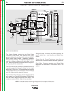
TROUBLESHOOTING & REPAIR
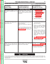
INPUT FILTER CAPACITOR CONDITION-
ING
Capacitor conditioning may be required if the machine
will not produce output after power is applied and
the
following two conditions exist:
The machine is connected to a supply of 380
v.a.c. or higher
and
Power has not been applied to the machine
for an extended period of time (months).
To condition the input filter capacitors:
1. Turn the Power Switch OFF
2. Remove any load and do not load the machine until
the capacitor conditioning is completed.
3. Turn the Power Switch ON and leave the machine
energized for at least 30 minutes.
4. Cycle the Power Switch OFF and on again .
The machine should now work normally. If not,contin-
ue with the Troubleshooting Section of this manual.
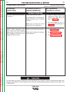
MATCHED PARTS
The following parts must be replaced in matched sets:
Output Diodes D1, D2, D3, D4, and D5.
Output Diodes D7, D8, D9, D10, and D11.
Note: On newer codes where Diode Modules are used
in place of individual diodes, both modules on a heat
sink assembly should be replaced if one fails.
Capacitor Bleeder Resistors: R1 & R9
Capacitors: C1 & C2
Capacitors C1, C2, C14 & C15 on 575 v.a.c. units.
Switch Boards proir to L10598-[ ]
F-4 F-4
Return to Section TOC Return to Section TOC Return to Section TOC Return to Section TOC
Return to Master TOC Return to Master TOC Return to Master TOC Return to Master TOC
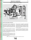
ADDITIONAL INFORMATION
OSCILLOSCOPE WARNING
Do not use oscilloscopes and other pieces of test equipment that are powered by 115 VAC. This
equipment should not be used with inverter-type machines, such as Invertec V300-PRO. There
are high voltages present, which are “floating” off case ground (floating ground). Connecting the
ground lead of a test probe (which may be connected to the case of the test equipment) to a
high voltage potential presents a shock hazard as well as the possibility of damage to the equip-
ment in question.