


NOTE: Lincoln Electric assumes no responsibility for liablilities resulting from board level troubleshooting. PC Board repairs will invalidate your factory warranty. Individual Printed Circuit Board Components are not available from Lincoln Electric. This information is pro-
vided for reference only. Lincoln Electric discourages board level troubleshooting and repair since it may compromise the quality of the design and may result in danger to the Machine Operator or Technician. Improper PC board repairs could result in damage to the
machine.
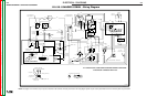
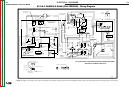
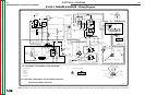
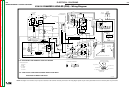
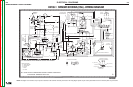
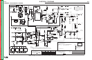
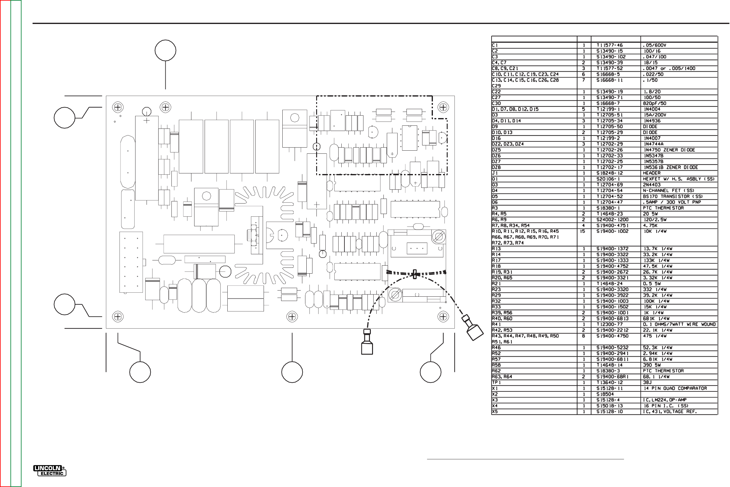
ELECTRICAL DIAGRAMS
G-11
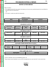
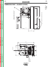
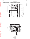
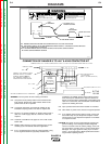
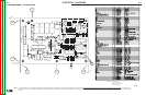
PC BOARD ASSEMBLY - IDLER/CONTROL
ITEM REQ’D
PART NO.
IDENTIFICATION
3.80
4.00
+.04
-
.20
0
0
.20
3.20 5.80
6.00
+.04
-
UNLESS OTHERWISE SPECIFIED:
CAPACITORS=MFD/VOLTS
RESISTORS=OHMS (1/4 WATT)
INDUCTANCE=HENRYS
X
X
X
X
X
X
X
X
x
x
x
x
x
x
x
x
x
x
x
x
x
x
x
x
x
x
x
x
x
x
x
X
X
X
X
XX
1.02
TP-D
R7
R61
R51
R50
R49
R48
R47
R44
R43
R29
R20
R10
R52
R40
R42
R60
R57
R46
R18
R54
R34
R8
R23
R33
R17
R32
R45
R16
R11
R56
R53
R19
R31
R12
R15
R13
R14
R39
Q1
C29
C28
C26
C15
C14
C13
C16
C30
C24
C23
C19
C11
C10
C12
C3
C7
C4
C1
C21
C9
C8
D10
D13
D9
DZ7
DZ6 DZ8
X3
X1
X4
TP1
J1
Q5
R3
R5
R4
R58
R21
R41
Q4
D3
R62
C27
X2
Q3
Q6
C2
R6
R9
R67
R68
R69
R70
R71 R72
R73 R74
R63
R64
R65
R66
X5
TP-B
A
-
TP
L8484-3
CONTROL
IDLER/FIELD
RANGER 8
TP-C
C22
D4
D11
D14
DZ5
DZ2
DZ3
DZ4
D16
D12
D8
D7
D15
D1
8484-3
L
7-14-2000D
G-11
Return to Section TOC Return to Section TOC Return to Section TOC Return to Section TOC
Return to Master TOC Return to Master TOC Return to Master TOC Return to Master TOC