


Return to Section TOC Return to Section TOC Return to Section TOC Return to Section TOC
Return to Master TOC Return to Master TOC Return to Master TOC Return to Master TOC
TROUBLESHOOTING & REPAIR
F-28 F-28
RANGER 8
CHARGING CIRCUIT TEST (continued)
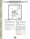
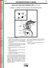
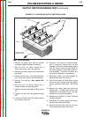
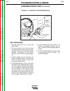
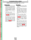
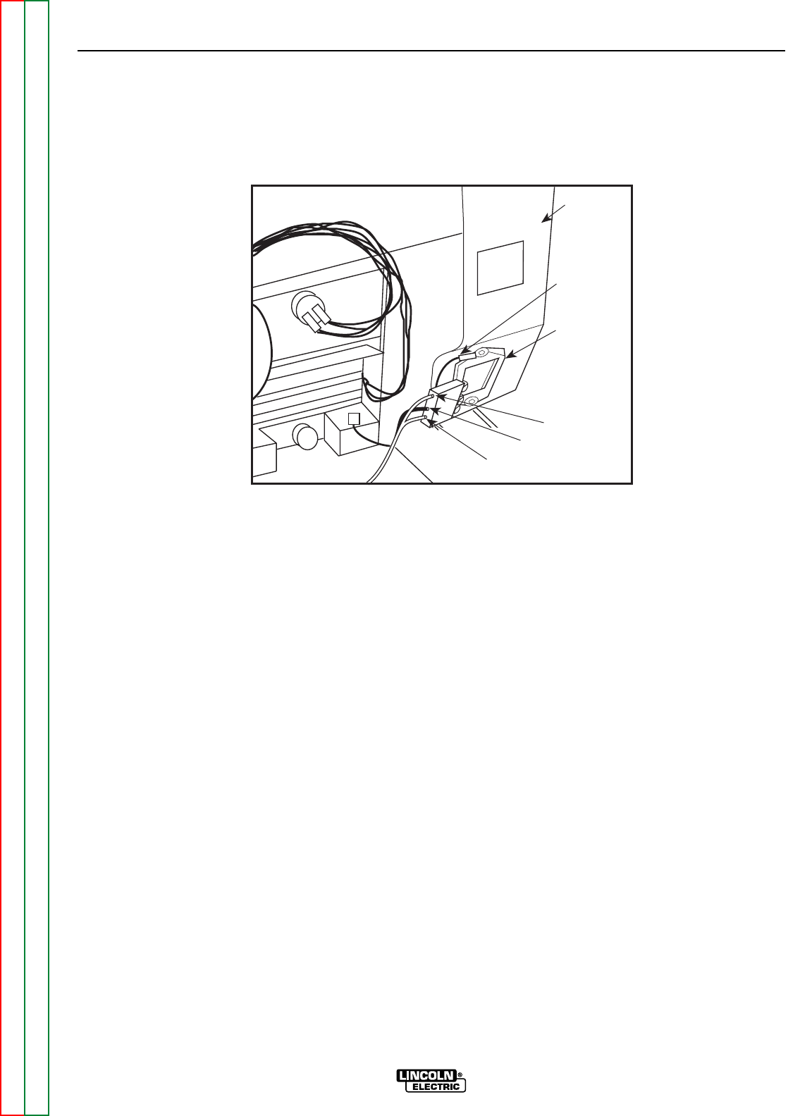
FIGURE F.6 – LOCATION OF VOLTAGE REGULATOR
Voltage
Regulator
Ground
Lead
(Green)
Engine
AC Lead
DC Lead
AC Lead
TEST PROCEDURE
1. Start the engine and run it at high idle
(3650 RPM).
2. Set the voltmeter for AC volts and place
one meter probe on each of the two out-
side leads that attach to the engine voltage
regulator. See Figure F.6 for location.
Check for 42-52 VAC at the voltage regula-
tor.
3. If the AC voltage is low or not present, the
engine flywheel alternator may be faulty.
This is an engine problem; consult your
local engine repair facility.
4. If the voltage reading is correct, then check
the output of the voltage regulator to deter-
mine the charging voltage for the battery.
Run the engine at high idle (3650 RPM).
Set the voltmeter for DC volts and place
one meter probe on the middle lead and
one probe on the green ground wire con-
nected to the voltage regulator. See Figure
F.6 for location. Check for 13-15 VDC.
5. If the DC voltage reading is incorrect or not
present, the voltage regulator may be
faulty. Replace the entire voltage regulator
module.
6. If the DC voltage reading is correct, check
the associated wiring and circuitry. See
the Wiring Diagram.