


Return to Section TOC Return to Section TOC Return to Section TOC Return to Section TOC
Return to Master TOC Return to Master TOC Return to Master TOC Return to Master TOC
TROUBLESHOOTING & REPAIR
F-53 F-53
RANGER 8
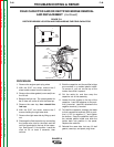
Be sure to follow the recommended static-
free methods for handling printed circuit
boards. Failure to do so can result in perma-
nent damage to the equipment.
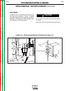
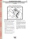
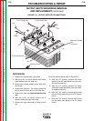
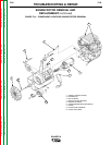
12. With the 1/4” nut driver, remove four
screws holding the printed circuit board.
13. Replace the old printed circuit board with
a new one.
14. Thread lead #3 back through the current
sensor on the printed circuit board and
reattach the lead to the 115 VAC recep-
tacle.
15. Connect current sensing leads 254 and
254A. See the Wiring Diagram for the
proper connections.
16. Connect the 12-pin molex plug.
17. Replace any cable ties that were cut dur-
ing the removal procedure.
18. With the 5/16” nut driver, install the
printed circuit board cover.
19. Reinstall the case side, fuel cap, lift bail
gasket, case top, and spark plug wires.
PRINTED CIRCUIT BOARD REMOVAL
AND REPLACEMENT (continued)
CAUTION