


Return to Section TOC Return to Section TOC Return to Section TOC Return to Section TOC
Return to Master TOC Return to Master TOC Return to Master TOC Return to Master TOC
TROUBLESHOOTING & REPAIR
F-49 F-49
RANGER 8
FIELD CAPACITOR AND/OR RECTIFIER BRIDGE REMOVAL
AND REPLACEMENT (continued)
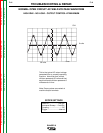
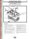
PROCEDURE - RECTIFIER BRIDGE
REMOVAL AND REPLACEMENT
1. To remove the rectifier bridge, first you will
have to remove the field capacitor. Follow
Steps 1 - 10 above.
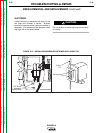
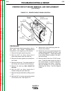
2. Depress the retainer clip on the molded
plastic holder and slide the rectifier bridge
out.
3. With the needle nose pliers, gently remove
the 6 wires from the rectifier bridge.
4. Replace the wires to their appropriate loca-
tions on the new rectifier bridge (See the
Wiring Diagram.):
Lead 200 and 200A are piggybacked on
the positive (+) terminal. Depending on the
bridge used, this corner may be beveled
and/or marked with a + sign.
Lead 201 and 201A are piggybacked on
the negative (-) terminal, which will always
be located diagonally across from the pos-
itive (+) terminal.
The two leads #7 and #9 are the AC side of
the bridge and attach to the other two cor-
ners. Either lead can go on either terminal.
5. Slide the bridge back into the molded plas-
tic holder until the retainer clip snaps it
securely in place. Snap the capacitor back
into the holder and then slide the unit back
into position in the panel.
6. Check that the leads are not grounded and
for clearance and tightness.
7. Reinstall the case side, fuel cap, lift bail gas-
ket, and case top.