


INSTALLATION
A-6 A-6
RANGER 8
Return to Section TOC Return to Section TOC Return to Section TOC Return to Section TOC
Return to Master TOC Return to Master TOC Return to Master TOC Return to Master TOC
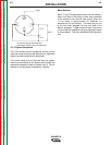
Angle of Operation
Internal combustion engines are designed to run in a
level condition which is where the optimum perfor-
mance is achieved. The maximum angle of operation
for the engine is 15 degrees from horizontal in any
direction. If the engine is to be operated at an angle,
provisions must be made for checking and maintain-
ing the oil at the normal (FULL) oil capacity in the
crankcase in a level condition.
When operating at an angle, the effective fuel capaci-
ty will be slightly less than the specified 10 gallons.
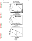
High Altitude Operation
If the Ranger 8 will be consistently operated at alti-
tudes above 5000 ft, a carburetor jet designed for high
altitudes should be installed. This will result in better
fuel economy, cleaner exhaust, and longer spark plug
life. It will not give increased power which is
decreased at higher altitudes. Engine horsepower is
reduced by 3.5% per 1000 feet for altitudes above 377
feet.
Do not operate a Ranger 8 with a high altitude jet
installed at altitudes below 5000 ft. This will result
in the engine running too lean and result in higher
engine operating temperatures which can shorten
engine life.
Contact your local Onan, Kohler or Honda Authorized
Dealer for high altitude jet kits that are available from
the engine manufacturer.
Muffler Relocation Shut off welder and allow
muffler to cool before touching muffler.
The Ranger 8 is shipped with the exhaust coming out
on the left side. The exhaust can be changed to the
opposite side by removing the two screws that hold
the exhaust port cover in place and installing the cover
on the opposite side. (Operating the Ranger 8 without
the cover in place will result in a higher noise level and
no increase in machine output.)
Location / Ventilation
The welder should be located to provide an unrestrict-
ed flow of clean, cool air to the cooling air inlets and to
avoid heated air coming out of the welder recirculating
back to the cooling air inlet. Also, locate the welder so
that engine exhaust fumes are properly vented to an
outside area.
Connection of Lincoln Electric
Wire Feeders
Shut off welder before making any electrical
connections.
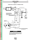
Wire Feed (Constant voltage)
Connection of the LN-25 to the Ranger 8
• Shut the welder off.
•
Connect the electrode cable from the LN-25 to the
“ELECTRODE” terminal of the welder. Connect
the work cable to the “TO WORK” terminal of the
welder.
• Position the welder “Polarity” switch to the desired
polarity, either DC (-) or DC (+).
• Position the “RANGE” switch to the “WIRE FEED”
position.
• Attach the single lead from the LN-25 control box
to the work using the spring clip on the end of the
lead - it carries no welding current.
• Place the idler switch in the “AUTO” position.
• Adjust wire feed speed at the LN-25 and adjust
the welding voltage with the output “CONTROL”
at the welder.
NOTE: The welding electrode is energized at all
times, unless an LN-25 with built-in contactor is used.
If the output “CONTROL” is set below “3”, the LN-25
contactor may not pull in.
CAUTION
WARNING
• Damage to the fuel tank may cause
fire or explosion. Do not
drill holes
in the Ranger 8 base or weld to the
Ranger 8 base.
WARNING
WARNING