


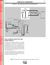
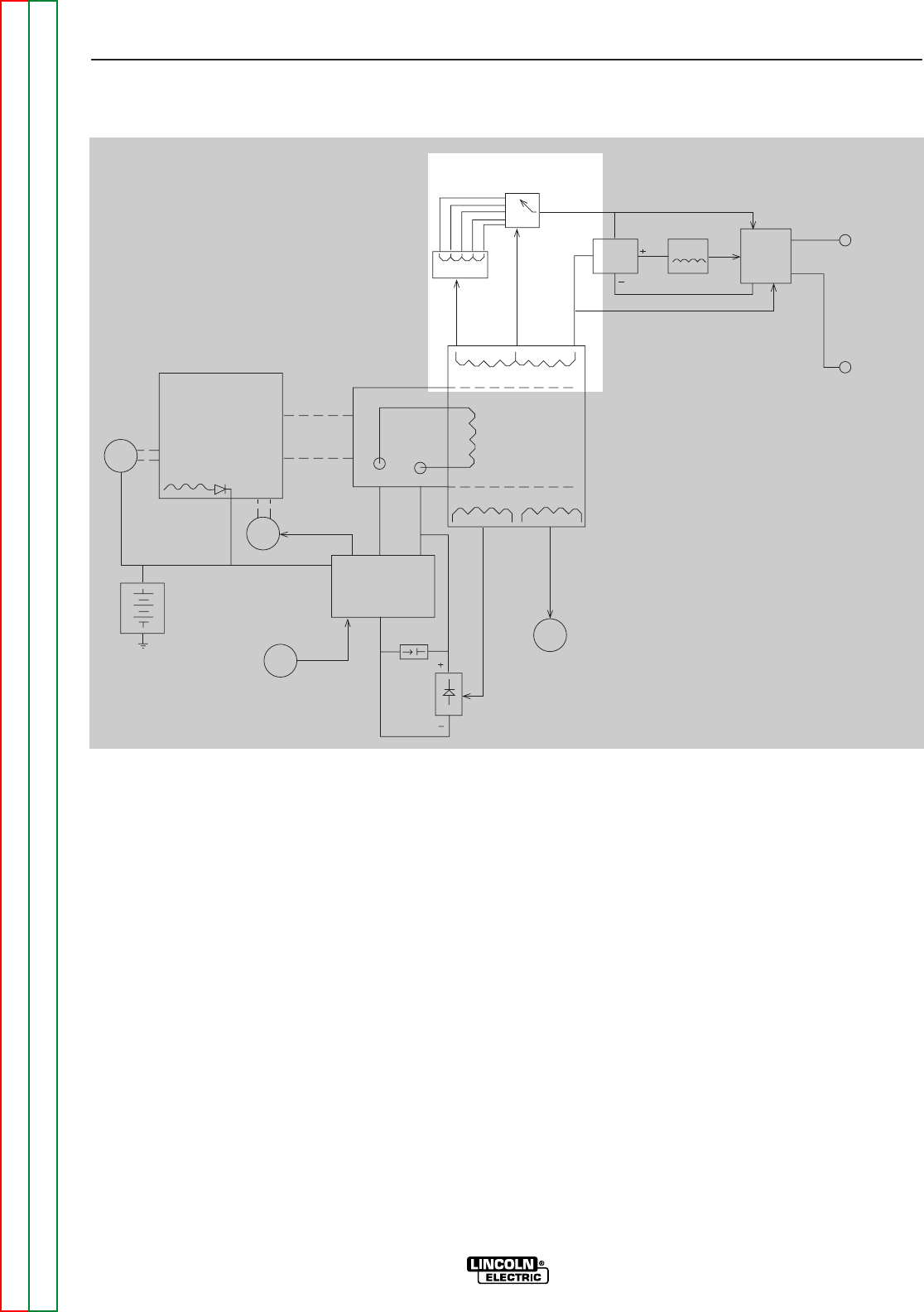
WELD WINDING, REACTOR, AND
RANGE SWITCH
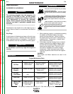
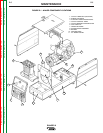
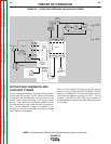
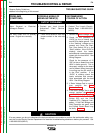
The stator weld winding is connected to the reactor
and range switch. The inductance in the reactor offers
an impedance to current flow. The reactor coil is
tapped at various points. As the range switch is ro-
tated, different amounts of reactor coil are brought into
the current path. As more turns of reactor are brought
into the circuit, the more impedance there is to current
flow. Simply stated, the more reactor in the circuit, the
lower the welding current.
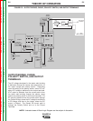
If a constant voltage is desired for wire feeding, then
the reactor is bypassed and the range switch is con-
nected to a tap on the stator weld winding to provide
a lower but “stiffer” output voltage.
THEORY OF OPERATION
E-4 E-4
RANGER 8
Return to Section TOC Return to Section TOC Return to Section TOC Return to Section TOC
Return to Master TOC Return to Master TOC Return to Master TOC Return to Master TOC
STARTER ENGINE
BATTERY
IDLER
SOLENOID
PRINTED
CIRCUT
BOARD
OUTPUT
CONTROL
MECHANICAL
ROTATION
FIELD
CAPACITOR
ROTOR
SLIP
RINGS
FIELD
BRIDGE
115 & 230VAC
RECEPTACLES
ROTOR
STATOR
STATOR
REACTOR
RANGE
SWITCH
OUTPUT
BRIDGE
CHOKE
AC
AC
POLARITY
SWITCH
ELECTRODE
TERMINAL
WORK
TERMINAL
FLYWHEEL
ALTERNATOR
FIGURE E.4 – WELD WINDING, REACTOR, AND RANGE SWITCH
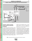
NOTE: Unshaded areas of Block Logic Diagram are the subject of discussion.