


Return to Section TOC Return to Section TOC Return to Section TOC Return to Section TOC
Return to Master TOC Return to Master TOC Return to Master TOC Return to Master TOC
TROUBLESHOOTING & REPAIR
F-22 F-22
RANGER 8
AUXILIARY AND FIELD WINDING TEST (continued)
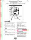
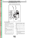
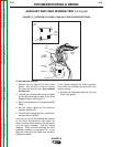
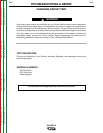
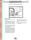
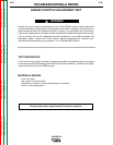
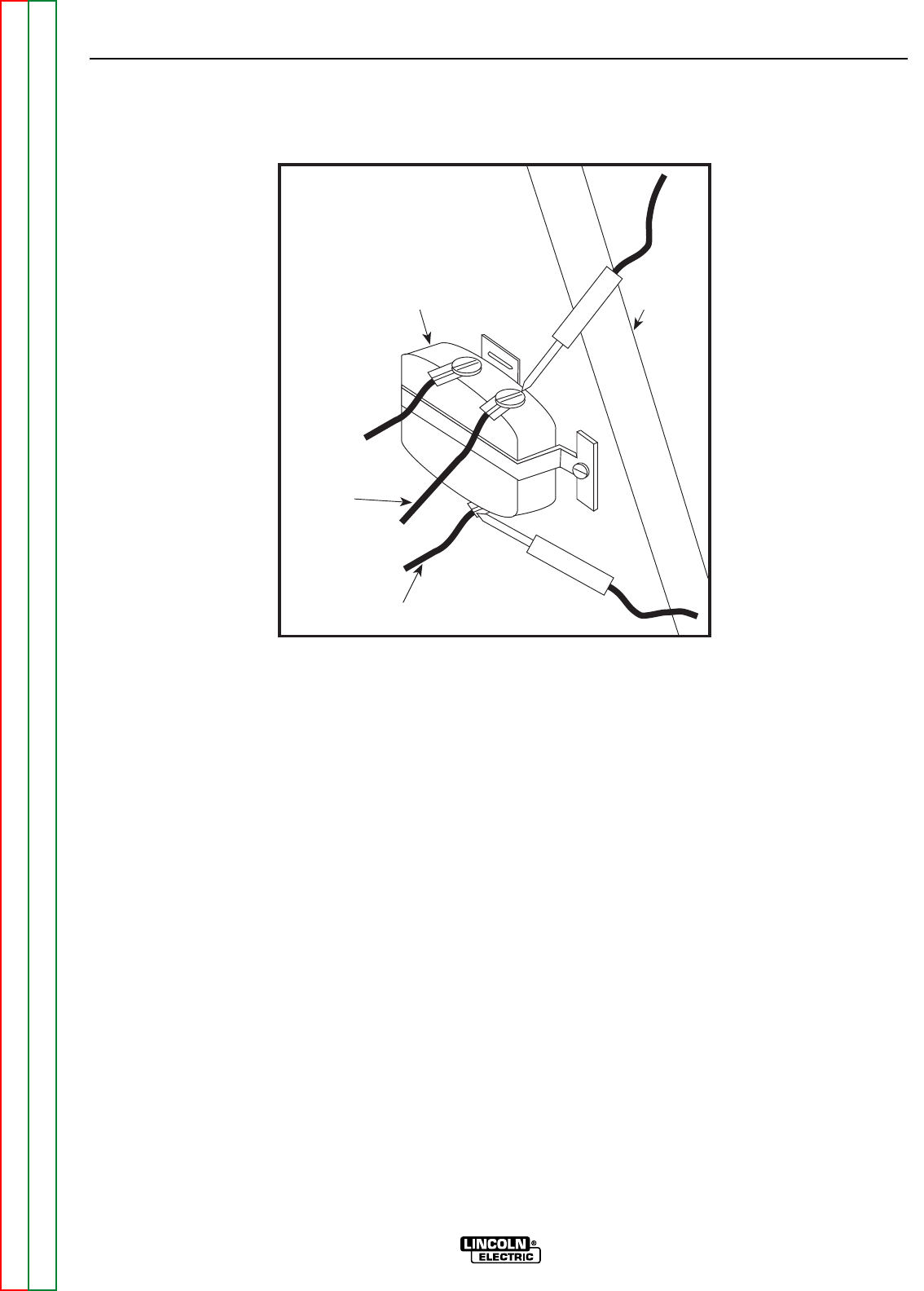
FIGURE F.3 – LOCATION OF LEADS #3 AND #5
Lead #3
Lead #5
115V
Receptacle
Machine
Case
Front
TEST PROCEDURE
To test the 115 VAC winding:
1. Remove the fuel cap and lift bail rubber
gasket. With the 5/16” nut driver, remove
the case top and left side; then reinstall the
fuel cap.
2. Connect the volt/ohmmeter probes to
leads #3 and #5 where they connect to the
115 VAC receptacle. See Figure F.3.
3. Start the engine and run it at high idle (3650
RPM).
4. Set the output control to the maximum
position (position 10).
5. Check the AC voltage reading. It should be
approximately 125 VAC.
To test the 230 VAC winding:
1. Remove the fuel cap and lift bail rubber
gasket. With the 5/16” nut driver, remove
the case top and left side; then reinstall
the fuel cap.
2. Connect the volt/ohmmeter probes to
leads #6 and #3 where they connect to the
230 VAC receptacle.
NOTE: It is easier to insert the probes direct-
ly into the receptacle to perform this test.
However, the probes may not reach in far
enough to make or keep a good connection.
In this case, before you start the gasoline
engine, insert two test probes into the recep-
tacle. Hold the test probes firmly in place to
measure voltage (Step 5).
3. Start the engine and run it at high idle (3650
RPM)
4. Set the output control to the maximum
position (position 10).
5. Check the AC voltage reading. It should be
approximately 240 VAC.