


Return to Section TOC Return to Section TOC Return to Section TOC Return to Section TOC
Return to Master TOC Return to Master TOC Return to Master TOC Return to Master TOC
TROUBLESHOOTING & REPAIR
F-5 F-5
RANGER 8
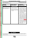
TROUBLESHOOTING GUIDE Observe Safety Guidelines
detailed in the beginning of this manual.
CAUTION
If for any reason you do not understand the test procedures or are unable to perform the test/repairs safely, con-
tact the Lincoln Electric Service Department for electrical troubleshooting assistance before you proceed. Call
1-800-833-9353 (WELD).
PROBLEMS
(SYMPTOMS)
POSSIBLE AREAS OF
MISADJUSTMENT(S)
RECOMMENDED
COURSE OF ACTION
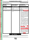
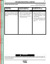
OUTPUT PROBLEMS
No weld output, the auxiliary
power (230-115VAC) is operating
normally. Engine runs normally.
1. Check the open circuit voltage
(OCV) at the welder output ter-
minals, engine at high idle (3650
RPM). Normal maximum is 73
to 80VAC. Normal DC maxi-
mum is 67 to 72VDC. If the
OCV is OK then proceed to
Step #2. If the OCV is not pre-
sent at the welder output termi-
nals, contact your local Lincoln
Authorized Field Service
Facility.
2. Check the welding cables,
clamps and electrode holder for
loose or broken connections.
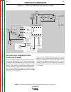
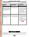
1. Disconnect lead W1 from the
Output Bridge (D1) and check
for the presence of 80VAC from
lead W1 to lead W2 on the main
stator winding. See wiring dia-
gram. If the AC voltage is NOT
present, the winding in the sta-
tor may be faulty. Check the
winding for continuity and test
to be sure it is NOT grounded to
the stator iron. Replace if nec-
essary. If the correct AC volt-
age is present, proceed to step
#2.
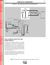
2. Check the Reactor, Range
Switch (S1) and associated
wires for loose or faulty connec-
tions. Check the reactor wind-
ing for continuity and test to be
sure it is NOT grounded to the
reactor iron.
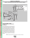
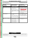
3. Check the Choke (L1), Polarity
Switch (S2) and associated
wires for loose or faulty connec-
tions. Check the choke winding
for continuity and test to be
sure it is NOT grounded to the
choke iron.
4. Check the weld output termi-
nals and associated wires for
loose or faulty connections.
5. Perform the Output Bridge Test.