


Return to Section TOC Return to Section TOC Return to Section TOC Return to Section TOC
Return to Master TOC Return to Master TOC Return to Master TOC Return to Master TOC
TROUBLESHOOTING & REPAIR
F-52 F-52
RANGER 8
PRINTED CIRCUIT BOARD REMOVAL AND REPLACEMENT
(continued)
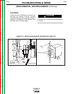
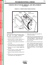
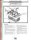
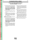
FIGURE F.12 - PRINTED CIRCUIT BOARD LOCATION
In Line
Connectors
Current
Sensor
Current
Sensing Leads
12 Pin
Molex Plug
5/16"
Screw (4)
PROCEDURE
Before starting the following procedure, refer to
the topic “PC Board Troubleshooting
Procedures” at the beginning of this section.
1. Remove the engine spark plug wires.
2. With the 5/16” nut driver, remove the 6
sheet metal screws from the case top.
3. Remove the rubber gasket (cover seal) from
the lift bail.
4. Remove the fuel cap. The rubber gasket for
the fill tube will come off with the case top.
5. Remove the case top, then reinstall the
fuel cap.
6. With the 5/16” nut driver, remove the 5
screws holding the right case side.
7. Remove the right case side by lifting up and
out.
8. WIth the 5/16” nut driver, remove the printed
circuit board cover. See Figure F.12.
9. Remove the 12-pin molex plug from the
Printed circuit board.
10. Detach the two in-line connectors from the
current sensing leads (254 and 254A - see
the Wiring Diagram.). These leads attach
to the current sensor located on the print-
ed circuit board.
11. Remove lead #3 from the 115 VAC recep-
tacle. Thread the lead through the hole in
the current sensor in order to separate it
from the printed circuit board. It will prob-
ably be necessary to cut any cable ties
restraining the wiring. Use the diagonal
cutters.