


OPERATION
B-4 B-4
CLASSIC I
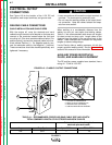
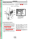
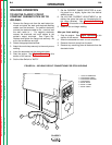
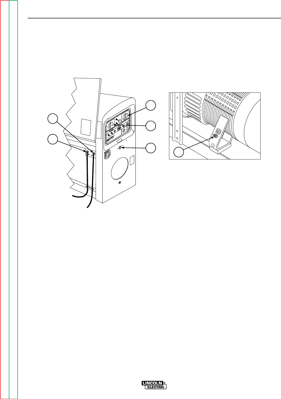
FIGURE B.1 – OUTPUT CONTROLS
1. CURRENT RANGE SELECTOR
2. FINE CURRENT ADJUSTMENT
3. 115 VOLT DC RECEPTACLE
4. WELD OUTPUT TERMINAL (–)
5. WELD OUTPUT TERMINAL (+)
6. GROUND STUD
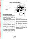
WELDER/GENERATOR CONTROLS
See Figure B.1 for the location of the following features:
1. CURRENT RANGE SELECTOR: Selects ranges
of continuous current output for constant current
stick or TIG applications and constant voltage wire
feed applications (with optional Wire Feed Module).
See
Control of Welding Current
for more informa-
tion.
2. FINE CURRENT ADJUSTMENT: Allows fine
adjustment of current within the selected output
range. See
Control of Welding Current
for more
information.
3. 120 VOLT DC RECEPTACLE: Connection point for
supplying 120V DC power to operate DC electrical
devices.
4. WELD OUTPUT TERMINAL (–) WITH FLANGE
NUT: Provides the connection point for either the
electrode holder or the work cable.
5. WELD OUTPUT TERMINAL (+) WITH FLANGE
NUT: Provides the connection point for either the
electrode holder or the work cable.
6. GROUND STUD: Provides a connection point for
connecting the machine case to earth ground. See
Machine Grounding
in the
Installation
section of
this manual.
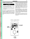
CONTROLS AND SETTINGS
The welder/generator controls are located on the
Output Control Panel of the machine case front.
E
ngine idler control and start/stop controls are also on
the case front. Welding output terminals and ground
stud are located on the machine right side, under the
door. See Figure B.1, B.2 and B.3 and the explanations
that follow.
6
3
5
4
2
1
Return to Section TOC Return to Section TOC Return to Section TOC Return to Section TOC
Return to Master TOC Return to Master TOC Return to Master TOC Return to Master TOC