


TROUBLESHOOTING & REPAIR
F-47 F-47
CLASSIC I
MAIN GENERATOR ARMATURE REMOVAL
AND REPLACEMENT (continued)
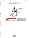
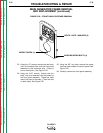
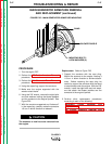
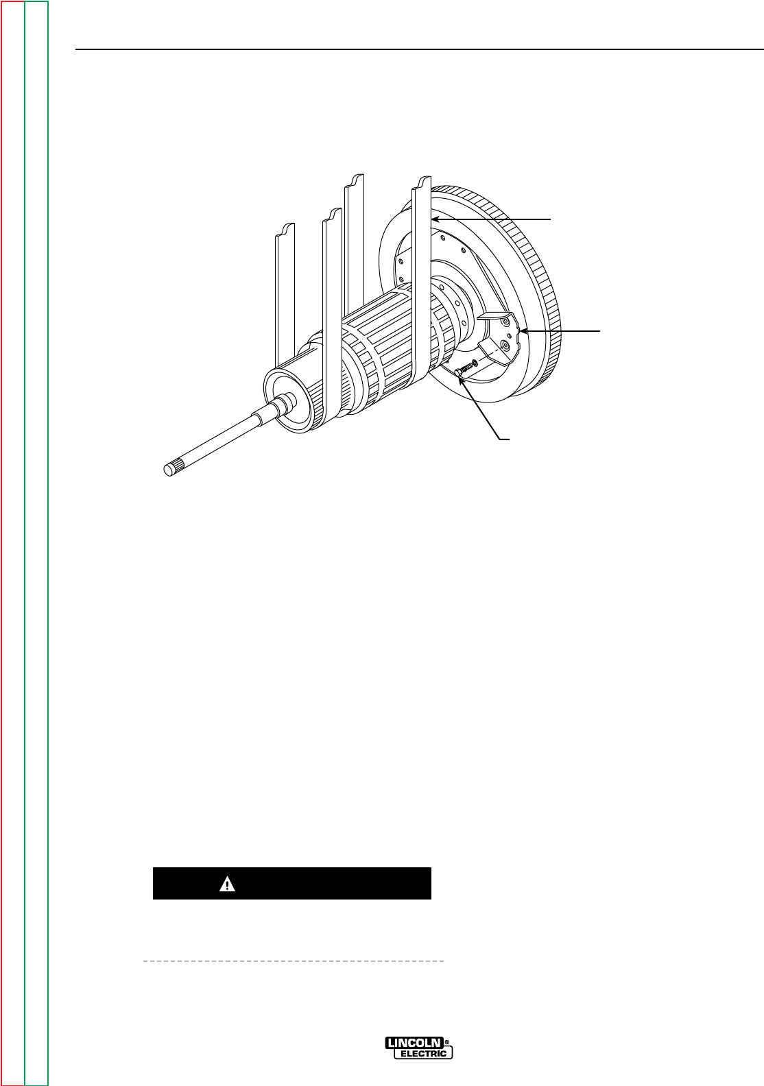
FIGURE F.25 – MAIN GENERATOR ARMATURE MOUNTING
MOUNTING BOLTS /
LOCK WASHERS (8)
BLOWER PADDLE
SLING
PROCEDURE
1. Turn the engine OFF.
2. Perform the
DC Exciter Armature Removal
procedure.
3. Perform the
Main Generator Frame Removal
procedure.
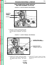
4. Using the rope sling, support the armature.
5. Make sure the engine supported with the
wood or steel blocks.
6. Using the 5/8” wrench, remove the eight bolts
and lock washers holding the blower paddles
and the armature to the engine flywheel. See
Figure F.25.
7. With the armature supported and “balanced”
in the rope sling, carefully rotate the armature
1/8 turn in either direction to release it.
The armature is now free to be removed from
the engine.
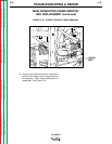
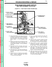
Replacement:
Refer to Figure F.25
1. Support the armature with the rope sling.
Mount the armature to the engine, rotating it
1/8 turn in either direction to achieve attach-
ment. Before removing the rope sling, be
careful to support the armature with the wood
or steel blocks under the engine. With the 5/8”
wrench, install the eight bolts and lock wash-
ers that attach the blower paddles and the
armature to the engine flywheel.
2. Perform other replacement procedures
according to each of the following:
Generator Frame Removal and
Replacement
DC Exciter Armature Removal and
Replacement
CAUTION
Return to Section TOC Return to Section TOC Return to Section TOC Return to Section TOC
Return to Master TOC Return to Master TOC Return to Master TOC Return to Master TOC