


TROUBLESHOOTING & REPAIR
F-28 F-28
CLASSIC I
FLASHING THE FIELDS (continued)
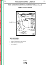
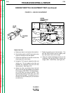
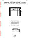
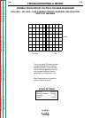
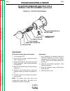
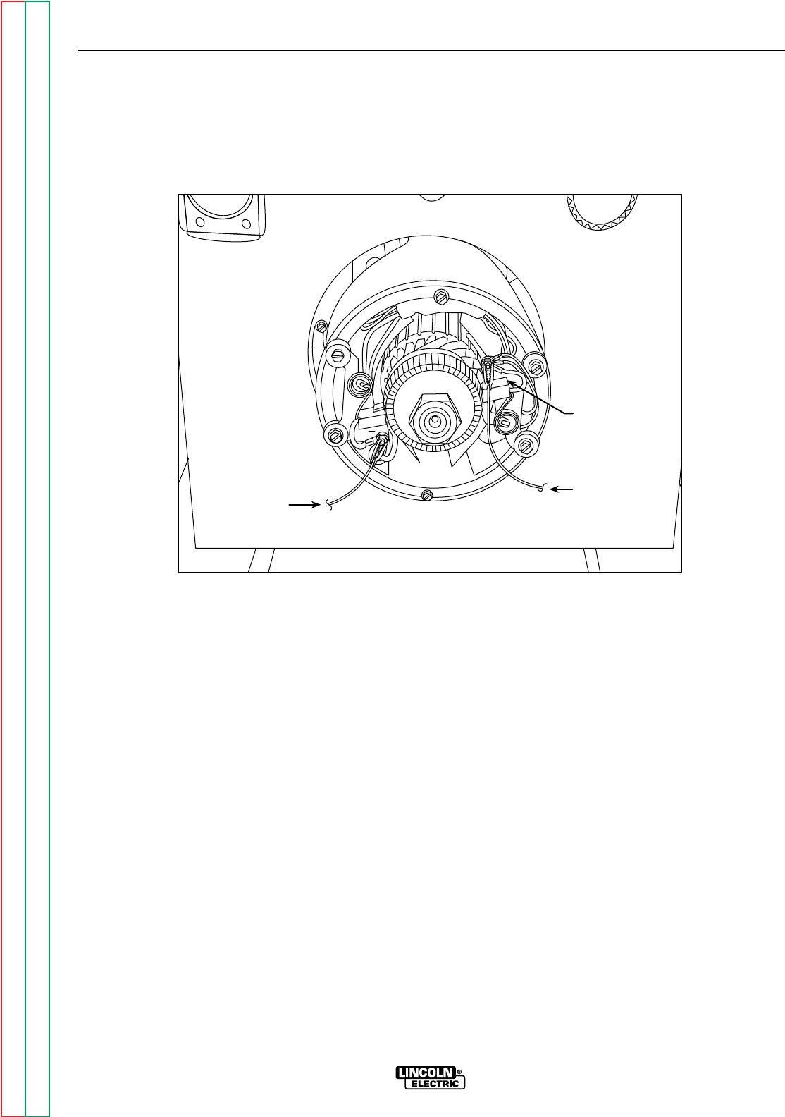
FIGURE F.11 - BRUSH HOLDER/BATTERY JUMPER CONNECTIONS
+
RAISE
EXCITER
BRUSH OFF
COMMUTATOR
TO POSITIVE
BATTERY
TERMINAL
TO NEGATIVE
BATTERY
TERMINAL
WARRANTY
3. Raise one exciter brush off the armature com-
mutator.
4. Using the jumper leads and the 12VDC bat-
tery, first attach the clip of one lead to the
POSITIVE terminal of the battery. Attach the
other end of this same lead to the right side
brush holder. See Figure F.11.
5. Carefully attach one clip of the other lead to
the NEGATIVE terminal of the battery. Attach
the other end of the same lead to the left side
brush holder for approximately five seconds.
Pull the lead away quickly to minimize arcing.
See Figure F.11.
6. Remove both leads from the brush holders
and the battery.
7. Install the brush removed in step 3.
8. Install the exciter cover using the 3/8” nut
driver.
9. Start the engine. The exciter should produce
DC output voltage.
Return to Section TOC Return to Section TOC Return to Section TOC Return to Section TOC
Return to Master TOC Return to Master TOC Return to Master TOC Return to Master TOC