


TROUBLESHOOTING & REPAIR
F-10 F-10
CLASSIC I
Observe Safety Guidelines
TROUBLESHOOTING GUIDE
detailed in the beginning of this manual.
CAUTION
If for any reason you do not understand the test procedures or are unable to perform the test/repairs safely, con-
tact the Lincoln Electric Service Department for electrical troubleshooting assistance before you proceed.
Call 1-800-833-9353.
PROBLEMS
(SYMPTOMS)
POSSIBLE AREAS OF
MISADJUSTMENT(S)
RECOMMENDED
COURSE OF ACTION
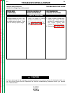
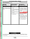
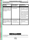
FUNCTION PROBLEMS
The engine will NOT go to high
speed when a load is applied to the
welding output terminals. The
engine does go to high speed when
a load is applied to the DC auxiliary
power receptacle.
1. Check welding cables for loose
or faulty connections.
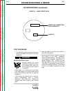
1. Check the reed switch (CR2) for
proper operation. The reed
switch should close when there
is current flow in the welding cir-
cuit.
2. Locate the red lead connected
to the idler PC board. While
leaving the red lead connected,
jumper the red lead to frame
ground. If the engine goes to
high speed, the fault is in the
reed switch or associated leads.
See the Wiring Diagram.
3. If the engine does NOT go to
high speed (in step 2), the idler
PC board may be faulty.
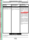
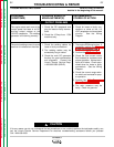
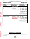
The engine will NOT go to high
speed when a load is applied to the
DC auxiliary receptacle. The
engine does go to high speed when
a load is applied to the welding out-
put terminals.
1. Check the auxiliary power plug
and associated leads for loose
or faulty connections.
2. The load may be too small. The
load must be above 150 watts.
1. Check the black “B” leads con-
nected to the idler PC board and
associated connections. See
the Wiring Diagram.
2. The idler PC board may be
faulty.
Return to Section TOC Return to Section TOC Return to Section TOC Return to Section TOC
Return to Master TOC Return to Master TOC Return to Master TOC Return to Master TOC