


TROUBLESHOOTING & REPAIR
F-14 F-14
CLASSIC I
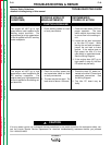
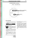
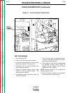
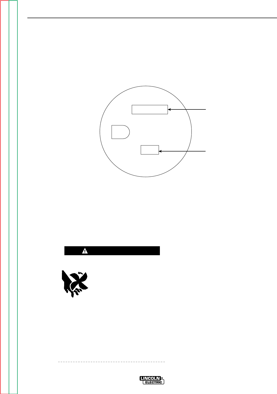
SERIES COIL CONNECTION
POINT (NEGATIVE)
POSITIVE
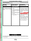
FIGURE F.1 – 120VDC RECEPTACLE
DC EXCITER TEST (continued)
TEST PROCEDURE
1. Turn off the engine and remove all external
loads to the welder terminals and auxiliary
receptacle.
MOVING PARTS can injure.
• Remove guards only when
necessary to perform service,
and replace them when the
service requiring their removal
is complete.
• Keep hands, hair, clothing and tools away
from V-belts, gears, fans, and all other moving
parts when starting, operating, or repairing
equipment.
• If fan guards are missing from a machine,
obtain replacements from a Lincoln
Distributor. (See Parts List.) Always use
greatest care when working near moving
parts.
2. Start the engine and put the idler switch in
the HIGH idle position.
3. Using the volt/ohmmeter, carefully check the
DC voltage at the 120V receptacle.
(Observe proper polarity. The large slot of
the receptacle is negative. See Figure F.1.)
Normal voltage is 125 - 135VDC, no load,
with the engine at the high idle speed of
1600 RPM. If the voltage is normal, the DC
exciter is functioning correctly. If the voltage
is low or not present, proceed to the next
step.
WARNING
Return to Section TOC Return to Section TOC Return to Section TOC Return to Section TOC
Return to Master TOC Return to Master TOC Return to Master TOC Return to Master TOC