


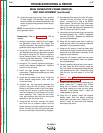
NOTE: Lincoln Electric assumes no responsibility for liablilities resulting from board level troubleshooting. PC Board repairs will invalidate your factory warranty. Individual Printed Circuit Board Components are not available from Lincoln Electric. This information is pro-
vided for reference only. Lincoln Electric discourages board level troubleshooting and repair since it may compromise the quality of the design and may result in danger to the Machine Operator or Technician. Improper PC board repairs could result in damage to the
machine.
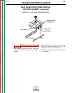
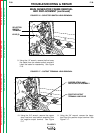
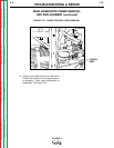
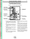
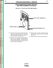
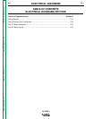
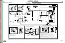
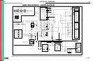
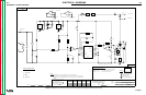
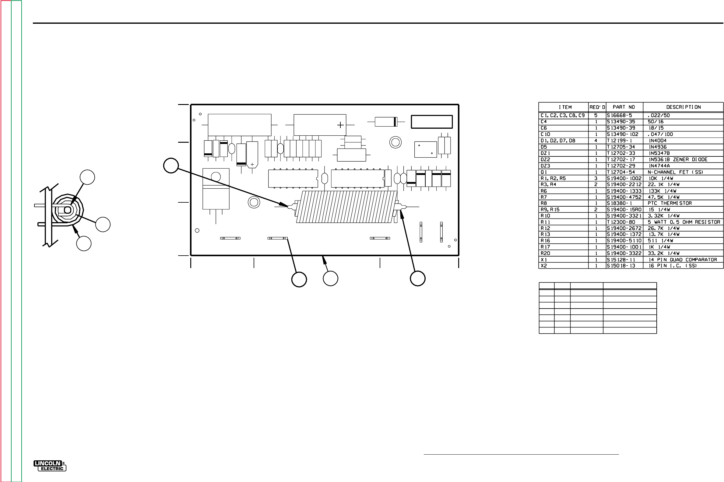
ELECTRICAL DIAGRAMS
G-5
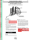
CLASSIC I
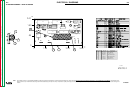
PC BOARD ASSEMBLY - IDLER PC BOARD
5-5-95A
M16723-2
+.05
-.02
+.05
-.02
0
0
2.40
1
2
3
6
7
5
4
IDLER
R15
R9
R17
R16
R13
R20
R5
R12
R3
R6
R7
R10
R4
R2
R1
C9
C8
C3
C2
C1
C10
C6
C4
D8
D7
D1
D2
DZ1
DZ2
X1 X2
B3
B2 B1
B4
B5
CR1
R11
R8
Q1
DZ3
D5
M16723-2
3.25
1.00
.85
1.80
3.25
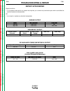
ITEM
REQ’D
PART NO.
DESCRIPTION
1
1
P.C. BOARD BLANK
2
5
3
T12012-4
T13157-14
TAB TERMINAL
4
5
6
CS000290
1
E1724-#10-2.10
1
1
1
7
T13344-3
T13344-2
REED SWITCH COIL
REED SWITCH COIL
REED SWITCH
2
M16723-B
CJ000015 E2387-#20-1.50
G-5
Return to Section TOC Return to Section TOC Return to Section TOC Return to Section TOC
Return to Master TOC Return to Master TOC Return to Master TOC Return to Master TOC