


ENGINE, MAIN GENERATOR
ARMATURE AND FRAME AND DC
EXCITER (CONTINUED)
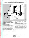
CURRENT RANGE SELECTOR
The selector switch acts as a course current adjust-
ment by allowing varying amounts of series windings to
be included in the welding current path. The series
coils and selector switch are connected in series with
the negative output terminal.
FINE CURRENT ADJUSTMENT
The field rheostat control functions as a fine output cur-
rent adjustment by controlling the current through the
shunt windings, thus controlling the amount of magnet-
ism created in the shunt field windings. Open circuit
weld voltage can also be controlled by the field rheo-
stat control.
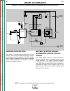
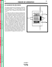
ENGINE IDLER CIRCUIT
The idler solenoid is mechanically connected to the
engine governor linkage. When welding current is
being drawn, the reed switch CR2 is closed. This
signals the idler PC board to release (deactivate) the
idler solenoid, which then lets the machine go to a high
speed condition. Also, when auxiliary power (115VDC)
is being used, the current is passed through a reed
switch coil located on the idler PC board, which signals
the PC board to release the idler solenoid.
When welding ceases or the auxiliary load is removed,
a preset time delay of about 15 seconds starts. After
approximately 15 seconds, the idler PC board acti-
vates the idler solenoid, and the machine will return to
a low idle speed condition.
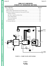
THEORY OF OPERATION
E-4 E-4
CLASSIC I
Return to Section TOC Return to Section TOC Return to Section TOC Return to Section TOC
Return to Master TOC Return to Master TOC Return to Master TOC Return to Master TOC