


A-5
INSTALLATION
LN-10
A-5
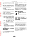
Electrode Routing
The electrode supply may be either from reels, Readi-
Reels, spools, or bulk packaged drums or reels.
Observe the following precautions:
a) The electrode must be routed to the wire drive unit
so that the bends in the wire are at a minimum,
and also that the force required to pull the wire
from the reel into the wire drive unit is kept at a
minimum.
b) The electrode is "hot" when the gun trigger is
pressed and must be insulated from the boom and
structure.
c) If more than one wire feed unit shares the same
boom and are not sharing the some power source
output stud, their wire and reels must be insulated
from each other as well as insulated from their
mounting structure.
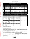
WIRE DRIVE SPEED RANGE
SELECTION
The rated speed and wire size range for each wire
drive head is shown in the SPECIFICATIONS in the
front of this section.
Control Speed Range Setting
The speed range is set up to match the wire feed
head connected to the LN-10 control by properly set-
ting the switch (S1) code on the control board inside
the control box. See OPERATION “Setting the DIP
Switches” for setting instructions.
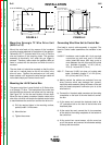
10 Series Wire Drive Ratio Selection
The 10 Series type drives include two external gear
sizes; a 1" dia. gear and a 1-1/2" dia. gear. The
smaller gear provides the low speed range ratio, and
the larger gear provides the high speed range ratio
per the SPECIFICATIONS in the front of this section.
The following procedure is for changing ratio of the 10
Series wire drive:
1) Pull open the Pressure Door.
2) Remove the Phillips head screw retaining the pin-
ion gear to be changed and remove the gear. If
the gear is not easily accessible or difficult to
remove, remove the feedplate from the gearbox.
To remove feedplate:
a) Loosen the clamping collar screw using a
3/16" Allen wrench. The clamping collar
screw is accessed from the bottom of the
feedplate. It is the screw which is perpen-
dicular to the feeding direction.
b) Loosen the retaining screw, which is also
accessed from bottom of feeder, using a
3/16" Allen wrench. Continue to loosen
the screw until the feedplate can be easily
pulled off of the wire feeder.
3) Loosen, but do not remove, the screw on the lower
right face of the feedplate with a 3/16" Allen
wrench.
4) Remove the screw on the left face of the feedplate.
If changing from high speed (larger gear) to low
speed (smaller gear), line the lower hole on the left
face of the feedplate with the threads on the
clamping collar. Line the upper hole with the
threads to install larger gear for high speed feeder.
If feedplate does not rotate to allow holes to line
up, further loosen the screw on right face of feed-
plate.
5) Install gear onto output shaft and secure with flat
washer, lock washer, and Phillips head screw
which were previously removed.
6) Tighten the screw on lower right face of feedplate.
7) Re-attach feedplate to wire feeder if removed in
Step 2.
8) Feedplate will be rotated out-of-position due to the
gear change. To re-adjust angle of feedplate:
a) Loosen the clamping collar using a 3/16"
Allen wrench. The clamping collar screw
is accessed from the bottom of the feed-
plate. It is the screw which is perpendicu-
lar to the feeding direction.
b) Rotate feedplate to the desired angle and
tighten clamping collar screw.
9) Make sure to properly set the switch (S2) code on
the control board inside the control box for the
new gear size installed. See OPERATION
“Setting the DIP Switch” for setting instructions.
Return to Section TOC Return to Section TOC Return to Section TOC Return to Section TOC
Return to Master TOC Return to Master TOC Return to Master TOC Return to Master TOC