


E-4
THEORY OF OPERATION
LN-10
E-4
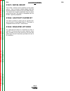
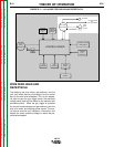
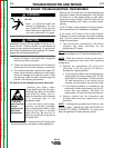
WIRE FEED HEAD AND
RECEPTACLE
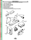
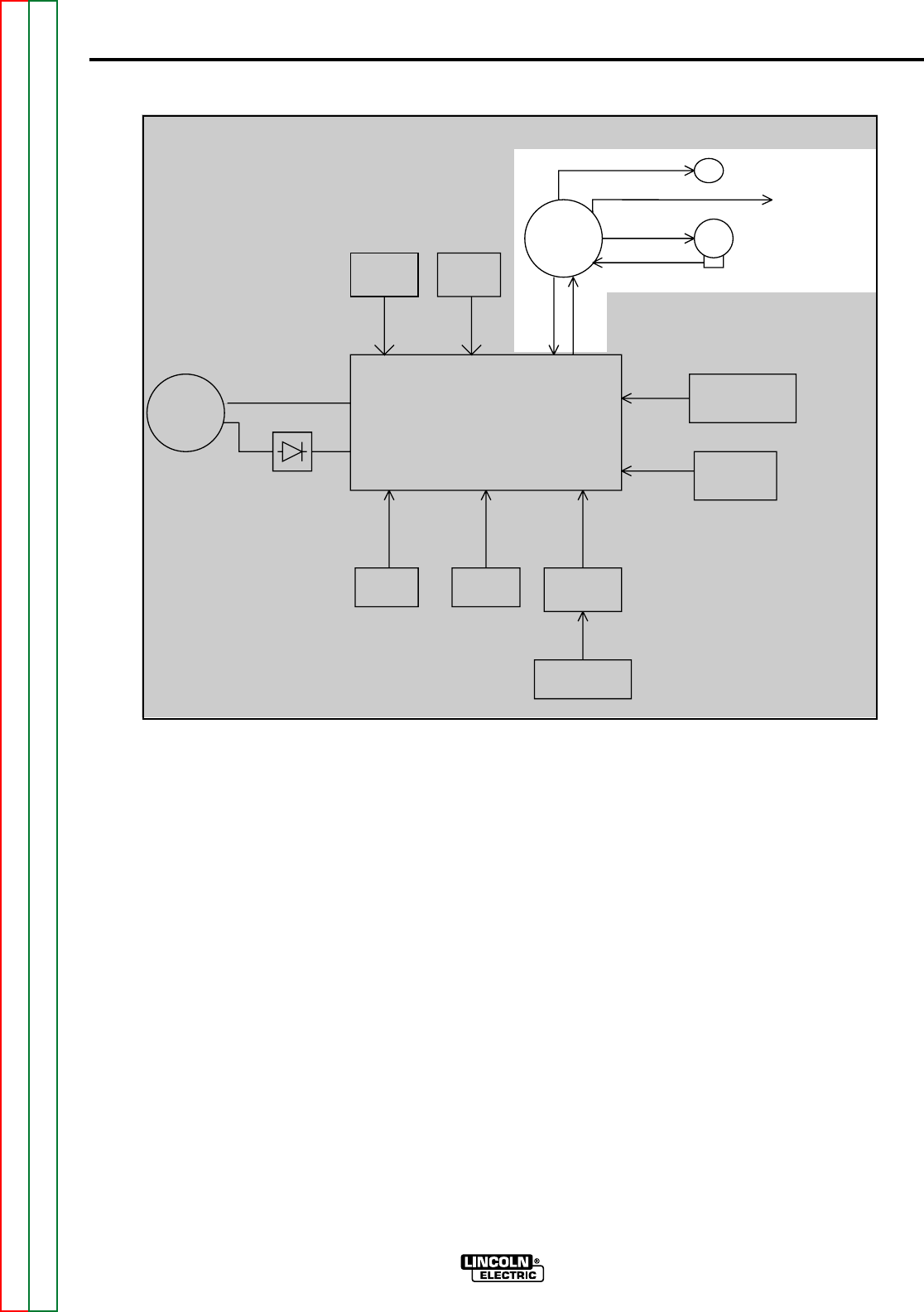
The leads to the drive motor, gas solenoid, and the
tach (hall effect device) are brought into the control
box via the wire drive receptacle. This 14-pin recepta-
cle also houses the gun trigger leads, the electrode
voltage sense lead and the leads for the optional dual
procedure switch. When the gun trigger is activated
the control board energizes the gas solenoid, then the
wire drive motor and welding power source. The con-
trol board receives tach feedback information and
adjusts the motor armature voltage to match the pre-
set wire feed speed.
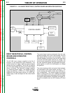
FIGURE E.3 — LN-10 WIRE FEED HEAD AND RECEPTACLE.
CONTROL BOARD
SOLENOID
WIRE DRIVE
RECEPTACLE
WIRE
DRIVE
MOTOR
TACH FEEDBACK
INPUT
CABLE
RECEPTACLE
42VAC
VOLTS
ENCODER
WFS
ENCODER
DISPLAY
BOARD
KEYPAD
GROUND
LEAD
PROTECTOR
CURRENT SENSING
REED SWITCH
TO GUN TRIGGER
AND
DUAL PROCEDURE
OPTIONAL
ROBOTIC
INTERFACE
MODULE
OPTIONAL
REMOTE
CONTROL
KIT
Return to Section TOC Return to Section TOC Return to Section TOC Return to Section TOC
Return to Master TOC Return to Master TOC Return to Master TOC Return to Master TOC