


A-6
INSTALLATION
LN-10
A-6
WIRE FEED DRIVE ROLL KITS
NOTE: The maximum rated solid and cored wire
sizes for each wire drive head and selected
drive ratio is shown on the SPECIFICATIONS
in the front of this section.
The electrode sizes that can be fed with each roll and
guide tube are stenciled on each part. Check the kit
for proper components.
Synergic 7F Wire Drives (K679) use 4-Roll drive roll
kits with 2 driven rolls, per Table C.1 in ACCES-
SORIES Section. These kits are common with those
used for the 4-Roll LN-7 GMA and LN-9 GMA Lincoln
Wire Feeders, but are not common with those used
with the 10 Series wire drive units. Installation instruc-
tions are included with the kits.
10 Series Wire Drives use 4-Roll drive roll kits with 4
driven rolls, per Table C.1.
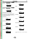
PROCEDURE TO INSTALL DRIVE
ROLL AND WIRE GUIDES
Synergic 7F Wire Drive 4-Roll Kits (KP655
and KP656)
1) Turn OFF welding power source.
2) Release both quick release levers by sliding the
levers sideways into the open positions.
3) Remove clamping screw & clamping collar from
the drive shaft closest to the incoming side of the
feeder.
4) Install drive roll onto keyed shaft. (Do not exceed
the maximum wire size rating of the wire drive.)
Replace collar and tighten clamping screw.
5) Back out the set screw for the middle guide tube.
Install the middle guide tube and slide it up against
the drive roll. DO NOT TIGHTEN THE MIDDLE
GUIDE AT THIS TIME.
6) Install the outgoing drive roll following the same
procedure as steps 3 & 4.
7) Center the middle guide between the two drive
rolls and tighten in place.
8) Back out the screws for the incoming and outgoing
guide tubes.
9) Install the longer guide tube in the rear hole near
the incoming drive roll. Slide the tube in until it
almost touches the roll. Tighten in place.
10) Install the remaining guide tube in the front hole.
Be certain that the proper plastic insert is used.
Fine wire chisel point tube must have largest
radius next to drive roll. Tighten in place.
11) Re-latch both quick release levers.
12) To start new electrode, straighten the first 6"
(150mm) and cut off the first 1" (25 mm). Insert
free end through the incoming tube. Press gun
trigger and push wire into the drive roll.
TO SET DRIVE ROLL PRESSURE, see “Drive Roll
Pressure Setting” in the OPERATION Section.
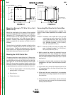
10 Series Wire Drive Roll Kit Installation
(KP1505 and KP1507)
1) Turn OFF Welding Power Source.
2) Pull open Pressure Door to expose rolls and wire
guides.
3) Remove Outer Wire Guide by turning knurled
thumb screws to unscrew from Feedplate.
4) Remove drive rolls, if any are installed, by pulling
straight off shaft. Remove inner guide.
5) Insert inner Wire Guide, groove side out, over the
two locating pins in the feedplate.
WARNING
Observe all additional Safety Guidelines detailed
throughout this manual.
ELECTRIC SHOCK can kill.
• Do not touch electrically live parts such
as output terminals or internal wiring.
•
When inching with gun trigger, electrode and
drive mechanism are “hot” to work and ground
and could remain energized several seconds
after the gun trigger is released.
• Turn OFF input power at welding power
source before installation or changing
drive roll and/or guide tubes.
• Welding power source must be connected
to system ground per the National
Electrical Code or any applicable local
codes.
• Only qualified personnel should
perform this installation.
Return to Section TOC Return to Section TOC Return to Section TOC Return to Section TOC
Return to Master TOC Return to Master TOC Return to Master TOC Return to Master TOC